POWER STEERING SYSTEM, Diagnostic DTC:C1524 and C1555
| DTC Code | DTC Name |
|---|---|
| C1524 | Motor Terminal Voltage |
| C1555 | Motor Relay Welding Failure |
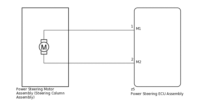
DESCRIPTION
The power steering ECU assembly supplies current to the power steering motor assembly (steering column assembly) through the motor circuit.
DTC No. |
Detection Item |
DTC Detection Condition |
Trouble Area |
Warning Indicate |
Return-to-normal Condition |
Note |
|---|---|---|---|---|---|---|
C1524 |
Motor Terminal Voltage |
Short (or open) in motor circuit or abnormal voltage in motor circuit |
|
EPS warning light: Comes on |
Ignition switch ON again |
- |
C1555 |
Motor Relay Welding Failure |
Predriver (Motor relay circuit) malfunction |
|
EPS warning light: Comes on |
Ignition switch ON again |
- |
WIRING DIAGRAM
CAUTION / NOTICE / HINT
If the power steering ECU assembly has been replaced, perform assist map writing and torque sensor zero point calibration.
PROCEDURE
CHECK POWER STEERING ECU ASSEMBLY
Start the engine.
-
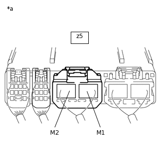
*a
Component with harness connected
(Power Steering ECU Assembly)
Measure the voltage according to the value(s) in the table below.
Standard Voltage
Tester Connection
Condition
Specified Condition
z5-1 (M1) - Body ground
Engine running and steering wheel being turned to left
6 to 8 V
z5-1 (M1) - Body ground
Engine running and steering wheel being turned to right
9 to 16 V
z5-2 (M2) - Body ground
Engine running and steering wheel being turned to left
9 to 16 V
z5-2 (M2) - Body ground
Engine running and steering wheel being turned to right
6 to 8 V
Result
Proceed to
OK
NG
INSPECT POWER STEERING MOTOR ASSEMBLY (STEERING COLUMN ASSEMBLY)
Disconnect the z5 power steering ECU assembly connector.
-
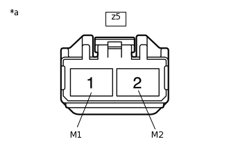
*a
Front view of wire harness connector
(to Power Steering ECU Assembly)
Measure the resistance according to the value(s) in the table below.
Standard Resistance
Tester Connection
Condition
Specified Condition
z5-1 (M1) - z5-2 (M2)
Always
0.1 to 1.0 Ω
z5-1 (M1) or z5-2 (M2) - Body ground
Always
1 MΩ or higher
Result
Proceed to
OK
NG