SFI SYSTEM, Diagnostic DTC:P0010
| DTC Code | DTC Name |
|---|---|
| P0010 | Camshaft Position "A" Actuator Circuit (Bank 1) |
DESCRIPTION
The Variable Valve Timing (VVT) system includes the ECM, camshaft timing oil control valve assembly and VVT controller. The ECM sends a target "duty-cycle" control signal to the camshaft timing oil control valve assembly. This control signal, applied to the camshaft timing oil control valve assembly, regulates the oil pressure supplied to the VVT controller. Camshaft timing control is performed based on engine operating conditions such as intake air volume, throttle position and engine coolant temperature.
The ECM controls the camshaft timing oil control valve assembly based on the signals from several sensors. The VVT controller regulates the intake camshaft angle using oil pressure through the camshaft timing oil control valve assembly. As a result, the relative positions of the camshaft and crankshaft are optimized, engine torque and fuel economy improve, and the exhaust emissions drop. The ECM detects actual valve timing using signals from the camshaft and crankshaft position sensors. The ECM performs feedback control and verifies target valve timing.

DTC No. |
Detection Item |
DTC Detection Condition |
Trouble Area |
MIL |
Memory |
|---|---|---|---|---|---|
P0010 |
Camshaft Position "A" Actuator Circuit (Bank 1) |
Open or short in camshaft timing oil control valve assembly circuit (3 trip detection logic). |
|
Comes on |
DTC stored |
The IC, built into the ECM, detects opens or shorts in the camshaft timing oil control valve assembly circuit.
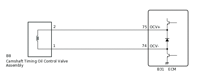
WIRING DIAGRAM
CONFIRMATION DRIVING PATTERN
DTC P0010 is detected when the engine idles for approximately 15 seconds.
CAUTION / NOTICE / HINT
Read freeze frame data using the GTS. The ECM records vehicle and driving condition information as freeze frame data the moment a DTC is stored. When troubleshooting, freeze frame data can help determine if the vehicle was moving or stationary, if the engine was warmed up or not, if the air fuel ratio was lean or rich, and other data from the time the malfunction occurred.
PROCEDURE
PERFORM ACTIVE TEST USING GTS (CONTROL THE VVT SYSTEM (BANK 1))
Connect the GTS to the DLC3.
Start the engine.
Turn the GTS on.
Warm up the engine.
Enter the following menus: Powertrain / Engine and ECT / Active Test / Control the VVT System (Bank 1).
Powertrain > Engine and ECT > Active Test
Tester Display
Control the VVT System (Bank1)
Check the engine speed when operating the camshaft timing oil control valve assembly using the GTS.
Result
Result
Proceed to
Engine changes from steady idling to rough idling or engine stalling
A
No change in engine speed
B
INSPECT CAMSHAFT TIMING OIL CONTROL VALVE ASSEMBLY
Inspect the camshaft timing oil control valve assembly.
Result
Proceed to
OK
NG
CHECK HARNESS AND CONNECTOR (CAMSHAFT TIMING OIL CONTROL VALVE ASSEMBLY - ECM)
Disconnect the camshaft timing oil control valve assembly connector.
Disconnect the ECM connector.
Measure the resistance according to the value(s) in the table below.
Standard Resistance
Tester Connection
Condition
Specified Condition
B8-2 - B31-75 (OCV+)
Always
Below 1 Ω
B8-1 - B31-74 (OCV-)
Always
Below 1 Ω
B8-2 or B31-75 (OCV+) - Body ground
Always
10 kΩ or higher
B8-1 or B31-74 (OCV-) - Body ground
Always
10 kΩ or higher
Result
Proceed to
OK
NG
NG REPAIR OR REPLACE HARNESS OR CONNECTOR