UPPER INSTRUMENT PANEL INSTALLATION
CAUTION / NOTICE / HINT
Use the same procedure for RHD and LHD vehicles.
The procedure listed below is for LHD vehicles.
A bolt without a torque specification is shown in the standard bolt chart.
PROCEDURE
INSTALL UPPER INSTRUMENT PANEL
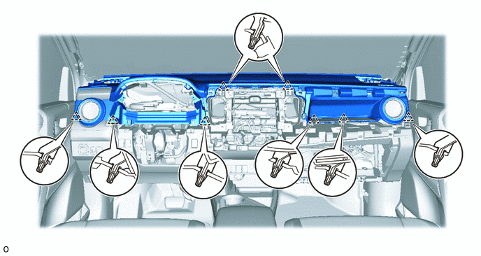
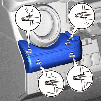
Attach the 8 clips to install the upper instrument panel.
for Single Type Airbag:
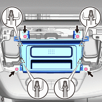
Install the 2 bolts <C> or <D>.
Install the 2 bolts <B>.
20 N*m
204 kgf*cm
15 ft.*lbf
Connect the connectors.
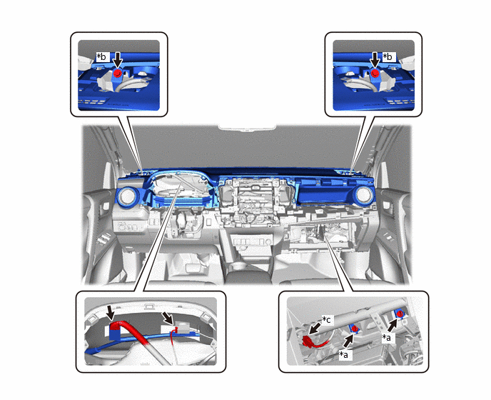
*a
Bolt <B>
*b
Bolt <C> or <D>
*c
Airbag Connector
-
-
-
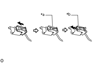
*a
Lock Slider
*b
Lock Position
Connect the airbag connector.
Note:When handling the airbag connector, take care not to damage the airbag wire harness.
Check that the lock slider is in the lock position.
for Dual Type Airbag:
Install the 2 bolts <C> or <D>.
Install the 2 bolts <B>.
20 N*m
204 kgf*cm
15 ft.*lbf
Connect the connectors.
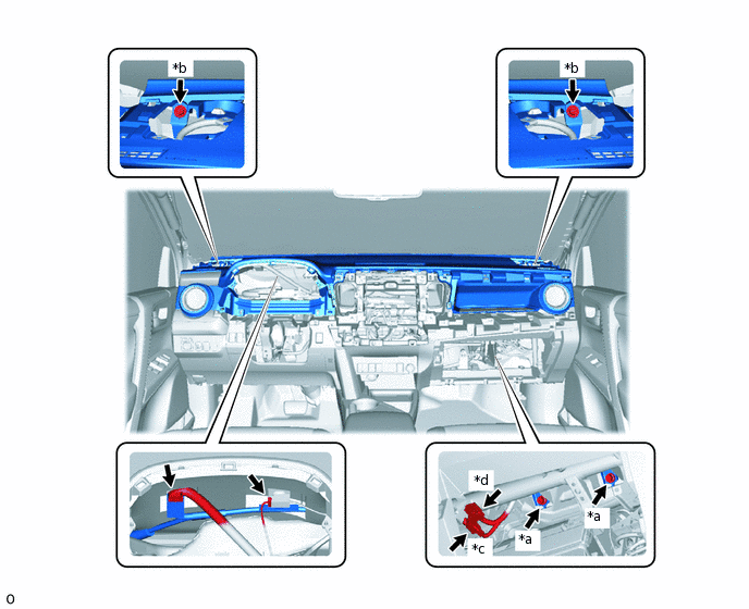
*a
Bolt <B>
*b
Bolt <C> or <D>
*c
Airbag Connector
-
-
-
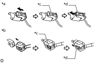
*a
Airbag Connector A
*b
Airbag Connector B
*c
Lock Slider
*d
Lock Position
Connect the 2 airbag connectors A and B.
Note:When handling the airbag connector, take care not to damage the airbag wire harness.
Check that the lock slider is in the lock position.
INSTALL FRONT PILLAR GARNISH LH
INSTALL FRONT PILLAR GARNISH RH
INSTALL FRONT NO. 2 SPEAKER ASSEMBLY (w/ Speaker)
INSTALL NO. 2 SPEAKER HOLE COVER
-
Attach the 2 guides, 2 clips and 2 claws to install the No. 2 speaker hole cover.
-
INSTALL NO. 1 SPEAKER HOLE COVER
Tip:Use the same procedure described for the No. 2 speaker hole cover.
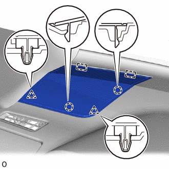
INSTALL GLOVE COMPARTMENT DOOR ASSEMBLY
-

Protective Tape
Apply protective tape as shown in the illustration.
Attach the 2 hinges to install the glove compartment door assembly.
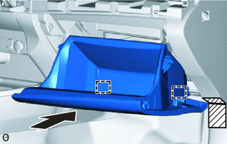
-
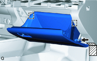
Protective Tape
While pushing in the sides of the glove compartment door assembly, attach the 2 stoppers.
Connect the glove compartment door stopper sub-assembly.
-
INSTALL UPPER INSTRUMENT CLUSTER FINISH PANEL
-
Attach the 4 clips to install the upper instrument cluster finish panel.
-
INSTALL NO. 2 INSTRUMENT PANEL GARNISH SUB-ASSEMBLY
Connect the connectors.
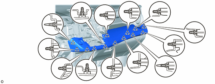
Attach the 13 clips to install the No. 2 instrument panel garnish sub-assembly.
INSTALL AIR CONDITIONING CONTROL ASSEMBLY
INSTALL HEADLIGHT DIMMER SWITCH
INSTALL COMBINATION METER ASSEMBLY
INSTALL NO. 1 INSTRUMENT CLUSTER FINISH PANEL
-
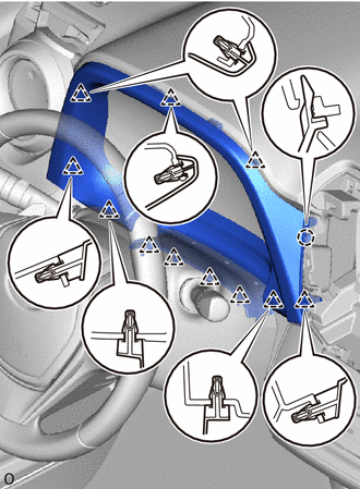
Attach the 11 clips and claw to install the No. 1 instrument cluster finish panel.
-
INSTALL STEREO OPENING COVER (w/o Audio)
-
Attach the 4 clips to install the stereo opening cover.
Install the 4 bolts.
-
INSTALL RADIO RECEIVER ASSEMBLY (w/ Audio, for Radio Receiver Type)
INSTALL RADIO AND DISPLAY RECEIVER ASSEMBLY (w/ Audio, for Radio and Display Type)
INSTALL TELLTALE LIGHT ASSEMBLY
INSTALL NO. 3 INSTRUMENT PANEL REGISTER ASSEMBLY
-
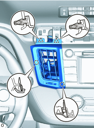
Attach the 2 clips and 2 claws to install the No. 3 instrument panel register assembly.
-
INSTALL NO. 4 INSTRUMENT PANEL REGISTER ASSEMBLY
-
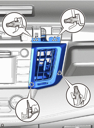
Attach the 3 clips and claw to install the No. 4 instrument panel register assembly.
-
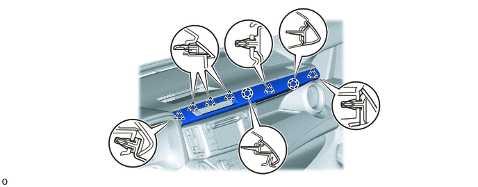
INSTALL CENTER NO. 1 INSTRUMENT CLUSTER FINISH PANEL
Attach the 6 clips and 2 claws to install the center No. 1 instrument cluster finish panel.
CONNECT CABLE TO NEGATIVE AUXILIARY BATTERY TERMINAL
Note:When disconnecting the cable, some systems need to be initialized after the cable is reconnected.
CHECK SRS WARNING LIGHT
INSTALL DECK BOARD ASSEMBLY