REAR LOWER ARM INSTALLATION
CAUTION / NOTICE / HINT
Use the same procedure for the RH and LH sides.
The procedure listed below is for the LH side.
PROCEDURE
INSTALL REAR NO. 1 SPRING BUMPER LH
-
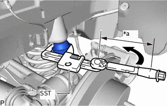
*a
Torque Wrench Fulcrum Length
Using SST, install the rear No. 1 spring bumper LH.
09922-10010
Specified tightening torque
30 N*m
306 kgf*cm
22 ft.*lbf
Tip:Calculate the torque wrench reading when changing the fulcrum length of the torque wrench.
When using SST (fulcrum length of 116.5 mm (4.587 in.)) + torque wrench (fulcrum length of 180 mm (7.087 in.)): 18.2 N*m (186 kgf*cm, 13 ft.*lbf)
-
TEMPORARILY INSTALL REAR NO. 2 SUSPENSION ARM ASSEMBLY LH
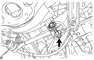
Temporarily install the rear No. 2 suspension arm assembly LH to the suspension member with the bolt and nut.
INSTALL REAR UPPER COIL SPRING INSULATOR LH
INSTALL REAR LOWER COIL SPRING INSULATOR LH
INSTALL REAR COIL SPRING LH
INSTALL REAR STABILIZER LINK ASSEMBLY LH
TEMPORARILY INSTALL REAR NO. 1 SUSPENSION ARM ASSEMBLY LH
-
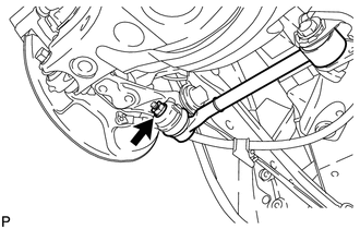
Temporarily install the rear No. 1 suspension arm assembly LH to the rear axle carrier with a new nut.
-
Insert the rear suspension toe adjust cam sub-assembly from the rear of the vehicle to install the rear No. 1 suspension arm assembly LH, and then temporarily install the No. 2 camber adjust cam with the nut.
-
TEMPORARILY INSTALL REAR SHOCK ABSORBER ASSEMBLY LH
STABILIZE SUSPENSION
TIGHTEN REAR NO. 2 SUSPENSION ARM ASSEMBLY LH
TIGHTEN REAR SHOCK ABSORBER ASSEMBLY LH
TIGHTEN REAR NO. 1 SUSPENSION ARM ASSEMBLY LH
-
Tighten the nut.
100 N*m
1020 kgf*cm
74 ft.*lbf
-
Tighten the nut of the rear No. 1 suspension arm assembly LH.
120 N*m
1224 kgf*cm
89 ft.*lbf
Note:Align the matchmarks on the rear suspension member and adjust cam.
-
INSTALL REAR HEIGHT CONTROL SENSOR SUB-ASSEMBLY LH
INSTALL REAR SUSPENSION ARM COVER LH (w/ Cover)
-
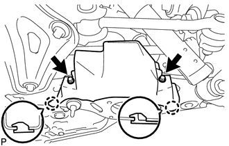
Insert the 2 claws of the rear suspension arm cover LH into the rear No. 2 suspension arm assembly LH.
Install the rear suspension arm cover LH with the 2 bolts.
12 N*m
122 kgf*cm
9 ft.*lbf
Note:Make sure that the 2 claws of the rear suspension arm cover are inserted.
-
INSTALL REAR WHEEL
INSPECT AND ADJUST REAR WHEEL ALIGNMENT