AIRBAG SYSTEM
-
FUNCTION OF MAIN COMPONENTS
-
The main components of the airbag system have the following functions:
Component Function Airbag ECU Assembly
-
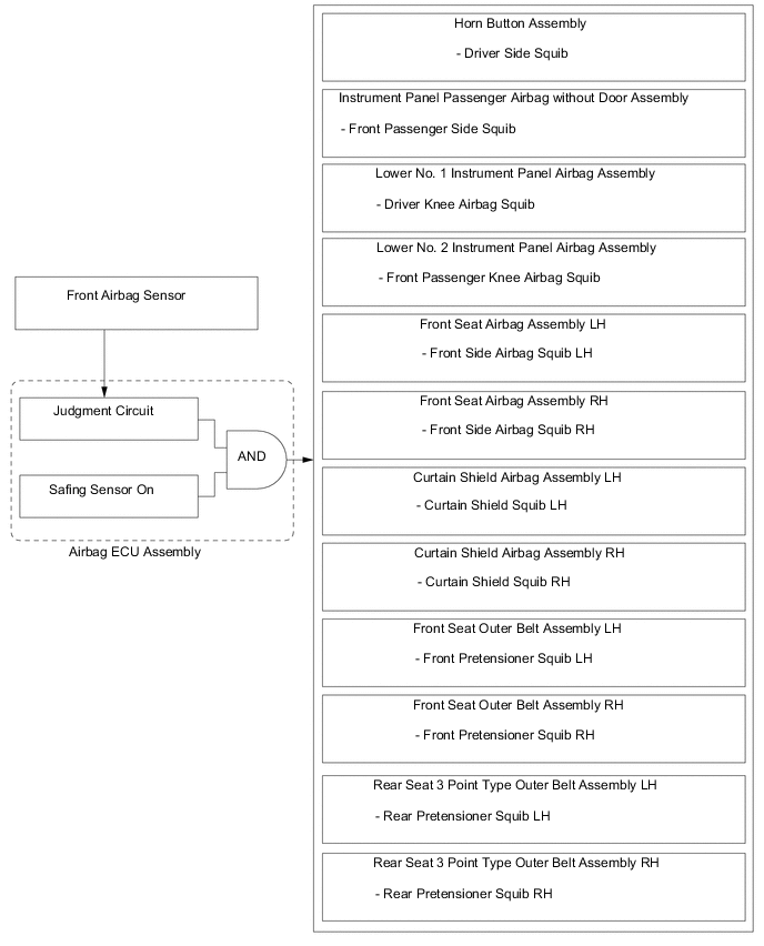
In the event of a frontal collision, the airbag ECU assembly receives signal from either of the front airbag sensors. The airbag ECU assembly receives the signal via its judgment circuit and also receives another signal from the safing sensor built into the airbag ECU assembly. After receiving a signal from at least one of the front airbag sensors and the safing sensor, the airbag ECU assembly determines whether the driver airbag, front passenger airbag, driver knee airbag, front passenger knee airbag, front seat airbags and curtain shield airbags should be deployed, and the front seat belt pretensioners and rear seat belt pretensioners should be activated. The airbag ECU assembly also diagnosis system malfunctions.
-
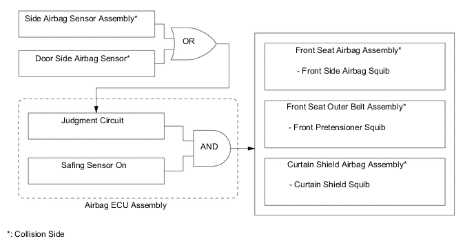
In the event of a side or rear side collision, the airbag ECU assembly receives signals from the side door airbag sensor, side airbag sensor assembly or rear airbag sensor. The airbag ECU assembly receives the signal via its judgment circuit and also receives another signal from the safing sensor built into the airbag ECU assembly. After receiving a signal from at least one of the side sensors and the safing sensor, the airbag ECU assembly determines whether the front seat airbag and curtain shield airbag should be deployed, and the front seat belt pretensioner should be activated. The airbag ECU assembly also diagnosis system malfunctions.
-
If the vehicle collides with a pedestrian, the airbag ECU assembly judges if ignition is necessary based on the signal from the pedestrian protection sensors and sends the ignition signal to the pop up hood lifter assembly.
-
Sends the collision detection signal to the ECM through the Controller Area Network (CAN) to operate fuel pump control.
-
Sends the collision detection signal to the main body ECU (multiplex network body ECU) to operate the collision door lock release function.
-
Sends the collision detection signal to the hybrid vehicle control ECU assembly to shut down the hybrid system power supply.
Horn Button Assembly Driver Side Squib Used as supplements to the seat belts to help reduce impact to the occupants. Instrument Panel Passenger Airbag without Door Assembly Front Passenger Side Squib Lower No. 1 Instrument Panel Airbag Assembly Driver Knee Airbag Squib Lower No. 2 Instrument Panel Airbag Assembly Front Passenger Knee Airbag Squib Front Seat Airbag Assembly LH/RH Front Side Airbag Squib LH/RH Curtain Shield Airbag Assembly LH/RH Curtain Shield Squib LH/RH Front Airbag Sensor LH/RH Based on the deceleration of the vehicle during a frontal collision, distortion is created in the sensor and is converted into an electrical signal. Side Airbag Sensor Assembly LH/RH Based on the deceleration of the vehicle during a side collision, distortion is created in the sensor and is converted into an electrical signal. Door Side Airbag Sensor LH/RH Rear Airbag Sensor LH/RH Based on the deceleration of the vehicle during a rear side collision, distortion is created in the sensor and is converted into an electrical signal. Front Seat Outer Belt Assembly LH/RH Front Pretensioner Squib LH/RH Used to help reduce impact to the occupants. Rear Seat 3 Point Type Outer Belt Assembly LH/RH Rear Pretensioner Squib LH/RH Seat Position Airbag Sensor Detects the slide position of the driver seat. Driver Seat Belt Buckle Switch (Front Seat Inner Belt Assembly LH*1/RH*2) Detects if the driver seat belt is fastened. Airbag Cut Off Switch Cylinder Sub-assembly*3 Suspends the instrument panel passenger airbag without door assembly operation. Air Conditioning Control Assembly*3 AIRBAG OFF Indicator Light Informs the occupants of the airbag cut off switch cylinder sub-assembly status. AIRBAG ON Indicator Light ECM Receives an airbag deployment signal from the airbag ECU assembly and stops to the fuel pump. Main Body ECU (Multiplex Network Body ECU) Receives an airbag deployment signal from the airbag ECU assembly and operates the collision door lock release function. Hybrid Vehicle Control ECU Assembly Receives the collision detection signal from the airbag ECU assembly during a collision and shuts down the hybrid system power supply by turning the System Main Relays (SMRs) off, in order to ensure safety. Skid Control ECU Assembly Sends the vehicle speed signal to the airbag ECU assembly. Pop Up Hood Sensor Assembly Pedestrian Protection Sensor LH/RH When the front bumper of the vehicle collides with a pedestrian, the pedestrian protection sensor detects changes in the pedestrian detection chamber pressure and sends signals to the airbag ECU assembly for the ignition judgment. Pop Up Hood Lifter Assembly LH/RH Consists of an inflator, cylinder and piston. On receiving the ignition signal from the airbag ECU assembly, the inflator is ignited, instantly pushing up the piston and raising the engine hood. Combination Meter Assembly SRS Warning Light Turns on to alert the driver when the airbag ECU assembly detects a malfunction in the airbag system. Multi-information Display Displays a warning message to inform the driver of a malfunction in the airbag system. Master Warning Light Turns on to alert the driver when the airbag ECU assembly detects a malfunction in the airbag system. Buzzer Sounds to warn the driver of a malfunction in the airbag system. *1: LHD models
*2: RHD models
*3: Models with airbag cut off switch cylinder
-
-
-
SYSTEM CONTROL
-
Airbag for Frontal Collision
-
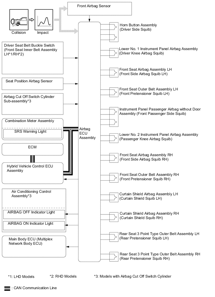
There are 8 airbags which deploy in the event of a frontal collision: the horn button assembly, instrument panel passenger airbag without door assembly, lower No. 1 instrument panel airbag assembly, lower No. 2 instrument panel airbag assembly, front seat airbag assemblies and curtain shield airbag assemblies. These airbags deploy simultaneously. The horn button assembly and instrument panel passenger airbag without door assembly use dual-stage control. In addition, each front pretensioner contained in a front seat outer belt assembly and each rear pretensioner contained in a rear seat 3 point type outer belt assembly are also activated.
-
The airbag ECU assembly detects the information in the table below from various sources in order to activate the dual-stage control.
-
For a frontal collision, if a front airbag sensor detects an impact, it informs the airbag ECU assembly. The airbag ECU assembly causes the horn button assembly, instrument panel passenger airbag without door assembly, lower No. 1 instrument panel airbag assembly, lower No. 2 instrument panel airbag assembly, front seat airbag assemblies and curtain shield airbag assemblies to deploy. Additionally, the airbag ECU assembly activates the seat belt pretensioners for the driver, front passenger and rear passengers.
Airbag Information Source Driver Extent of Impact
-
Front Airbag Sensor LH or RH
-
Airbag ECU Assembly
Driver Seat Position Seat Position Airbag Sensor Seat Belt Condition Driver Seat Belt Buckle Switch (Front Seat Inner Belt Assembly LH*1/RH*2) (Non-contact Type) Front Passenger Extent of Impact
-
Front Airbag Sensor LH or RH
-
Airbag ECU Assembly
*1: LHD models
*2: RHD models
-
-
Deceleration sensors used for the airbag system are installed on various parts on the vehicle and calculate the deceleration (or acceleration) rate of each part during a collision.
-
Depending on the situation, the airbag ECU assembly sends a deployment signal to each airbag and pretensioner based on the information from each sensor.
-
Frontal collision signals are produced based on the information from the airbag ECU assembly and front airbag sensors. Frontal collision signals are used to deploy all the airbags and activate all the pretensioners as indicated in the table below.
Figure 1. Frontal Collision
-
-
Airbag for Side/Rear Side Collision
-
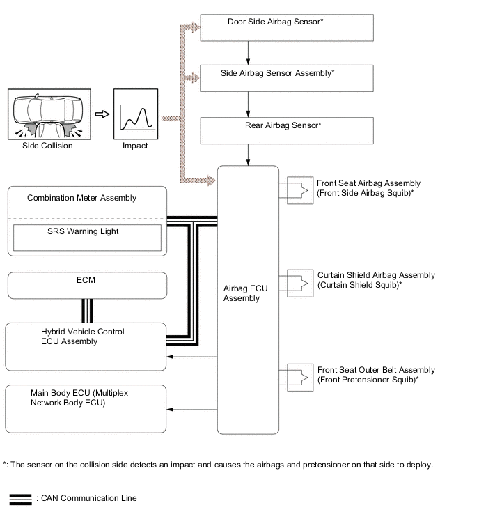
There are 2 airbags which deploy in the event of a severe side collision: the front seat airbag assembly and curtain shield airbag assembly. These airbags deploy simultaneously. Additionally, at the same time, the front seat belt pretensioner is also activated.
-
For a side collision, if the door side airbag sensor or side airbag sensor assembly detects an impact, it informs the airbag ECU assembly, and the airbag ECU assembly causes the front seat airbag assembly and curtain shield airbag assembly to deploy simultaneously, and activates the front seat belt pretensioner.
-
The front seat airbag assembly and curtain shield airbag assembly are deployed and the front pretensioner in the front seat outer belt assembly is activated based on signals from the door side airbag sensors or side airbag sensor assembly and airbag ECU assembly.
Figure 2. Side Collision
-
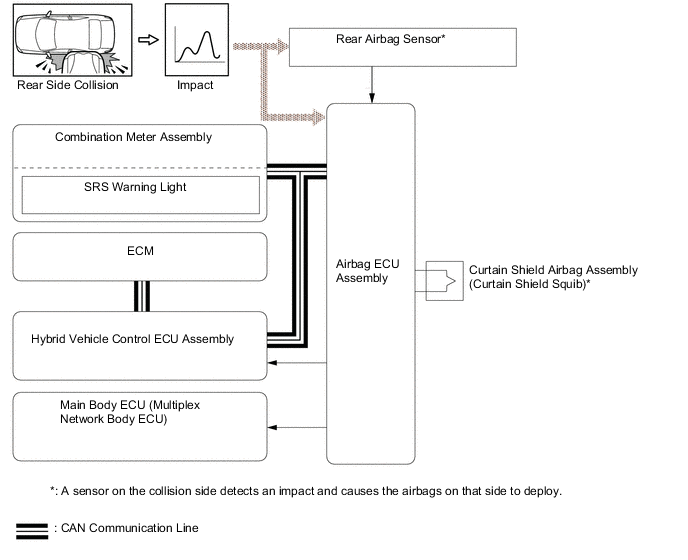
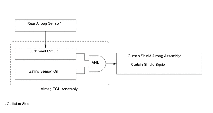
For a rear side collision, if the rear airbag sensor detects an impact, it informs the airbag ECU assembly and the airbag ECU assembly causes the curtain shield airbag assembly to deploy.
-
The curtain shield airbag assembly is deployed based on signals from the rear airbag sensor and the airbag ECU assembly.
Figure 3. Rear Side Collision
-
-
Pedestrian Collision
-
The pop up hood operates when the pressure change is detected in the chamber of the pop up hood sensor assembly in case that the vehicle (front bumper) collides with a pedestrian.
-
The pop up hood is designed to pop up in a collision with a pedestrian when driving at approximately 25 to 55 km/h (16 to 34 mph).
Note
The pop up hood pops up when the front bumper collides with a pedestrian or any obstacle.
-
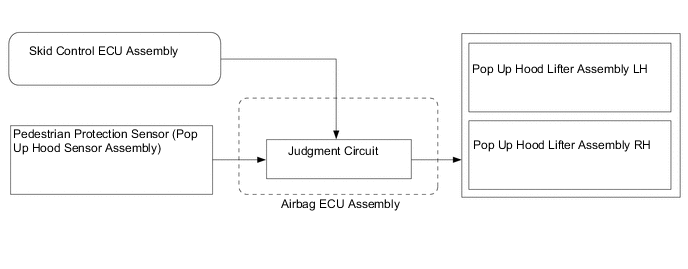
For a pedestrian collision, if a pedestrian protection sensor detects an impact, it informs the airbag ECU assembly and causes the pop up hood lifter assemblies to be deployed.
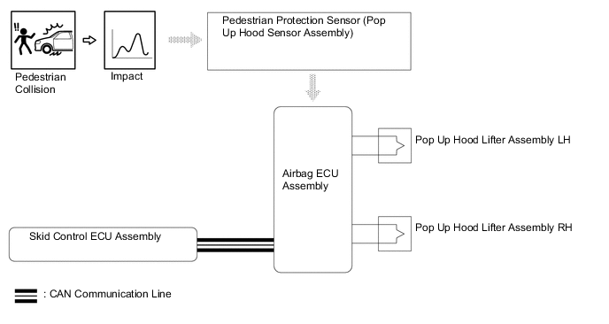
-
The pop up hood lifter assemblies are deployed based on signals from the pedestrian protection sensors and skid control ECU assembly.
-
-
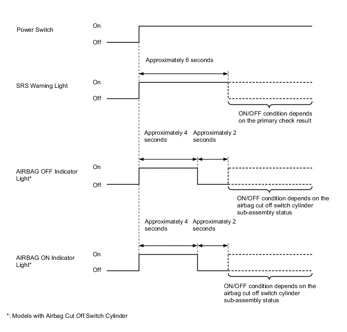
Primary Check Illumination Control
-
After the power switch is turned on (IG), the airbag ECU assembly illuminates the SRS warning light in the combination meter assembly for approximately 6 seconds and conducts the primary check. During the primary check, the ignition of airbags is prohibited and a diagnosis of the airbag ECU assembly is performed. If a malfunction is detected during the primary check, the SRS warning light will remain on even after 6 seconds have elapsed.
-
After the power switch is turned on (IG), the airbag ECU assembly operates the passenger airbag ON/OFF indicator lights as shown below to check for an open in the indicator light circuits.
-
-
-
DIAGNOSIS
-
If the airbag ECU assembly detects a malfunction in the SRS airbag system, the airbag ECU assembly stores the malfunction data in memory as Diagnostic Trouble Codes (DTCs) in addition to illuminating the SRS warning light.
-
The airbag ECU assembly outputs malfunction data and 5-digit Diagnostic Trouble Codes (DTCs) to the Global TechStream (GTS).
-
The 5-digit DTCs can be read by connecting the Global TechStream (GTS) to the DLC3. For details, refer to the Repair Manual.
-
If the SRS airbags deploy, the airbag ECU assembly will turn on the SRS warning light. However, unlike an ordinary malfunction, a DTC will not be stored. The SRS warning light cannot be manually turned off. It is necessary to replace the airbag ECU assembly with a new one.
-