МАСЛЯНЫЙ НАСОС СНЯТИЕ
-
DISCHARGE FUEL SYSTEM PRESSURE
CAUTION:
-
Do not disconnect any part of the fuel system until you have discharged the fuel system pressure.
-
Even after discharging the fuel pressure, place a cloth or equivalent over fittings as you separate them to reduce risk of fuel spray on yourself or in the engine compartment.
-
Disconnect the cable from the negative (-) battery terminal.
CAUTION:
Wait at least 90 seconds after disconnecting the cable from the negative (-) battery terminal to prevent airbag and seat belt pretensioner activation.
-
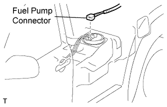
Disconnect the fuel pump connector.
-
Connect the cable to the negative (-) battery terminal.
-
Start the engine. After the engine has stopped on its own, turn the ignition switch OFF.
Tech Tips
DTC P0171/25 (system too lean) may be set.
-
Crank the engine again, then check that the engine does not start.
-
Loosen the fuel tank cap, then discharge the pressure in the fuel tank completely.
-
Connect the fuel pump connector.
-
-
DISCONNECT CABLE FROM NEGATIVE BATTERY TERMINAL
CAUTION:
Wait at least 90 seconds after disconnecting the cable from the negative (-) battery terminal to prevent airbag and seat belt pretensioner activation.
-
REMOVE ENGINE ASSEMBLY
-
Remove the engine from the vehicle Click here.
-
-
INSTALL ENGINE TO STAND
-
Place the engine onto the stand.
-
-
REMOVE IGNITION COIL
-
Remove the bolt and ignition coil.
-
-
REMOVE SPARK PLUG
-
REMOVE THROTTLE BODY
-
Отсоедините датчик положения дроссельной заслонки и разъем электродвигателя привода.
-
Отсоедините 2 перепускных шланга охлаждающей жидкости.
-
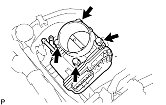
Выверните 4 болта и снимите корпус дроссельной заслонки.
-
Снимите прокладку.
-
-
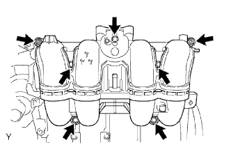
REMOVE INTAKE MANIFOLD
-
Disconnect the crankshaft position sensor from the clamp.
-
Remove the 5 bolts, 2 nuts, intake manifold and gasket.
-
-
REMOVE GENERATOR
-
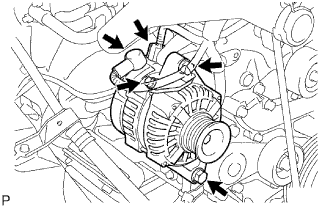
Remove the nut, bolt and generator wire.
-
Disconnect the generator connector.
-
Remove the 2 bolts and generator.
-
-
REMOVE NO. 1 COMPRESSOR MOUNTING BRACKET
-
Remove the 5 bolts and No. 1 compressor mounting bracket.
-
-
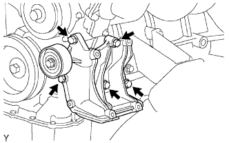
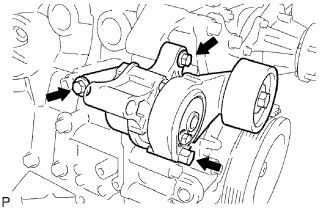
REMOVE DRIVE BELT TENSIONER
-
Remove the 3 bolts and belt tensioner.
-
-
REMOVE WATER INLET
-
Remove the bolt, 2 nuts, water inlet and gasket.
-
-
REMOVE THERMOSTAT
-
Remove the thermostat and gasket.
-
-
REMOVE NO. 1 IDLER PULLEY
-
Remove the bolt, pulley plate, idler pulley and spacer.
-
-
REMOVE NO. 1 WATER BY-PASS PIPE
-
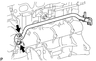
Remove the 2 nuts, water by-pass pipe and gasket.
-
-
REMOVE OIL FILLER CAP
-
REMOVE CYLINDER HEAD COVER
-
Remove the 19 bolts, 2 nuts, head cover and 2 gaskets.
-
-
REMOVE CAMSHAFT POSITION SENSOR
-

Отсоедините разъем датчика.
-
Выверните болт и снимите датчик.
-
-
REMOVE CRANKSHAFT PULLEY
-
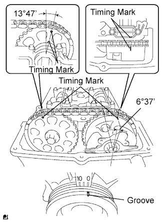
Turn the crankshaft pulley, and align its groove with timing mark 0 of the timing chain cover.
-
Check that the timing marks of the camshaft timing gear and sprocket are aligned with the timing marks of the No. 1 bearing cap, as shown in the illustration.
-
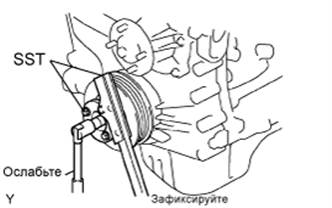
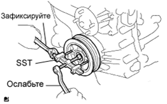
Using SST, loosen the pulley bolt.
- SST
- 09213-54015 ( 91651-60855 )
-
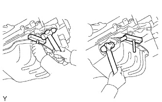
Using SST, remove the pulley bolt and pulley.
- SST
- 09330-00021
- 09950-50013 ( 09951-05010, 09952-05010, 09953-05010, 09954-05021 )
-
-
REMOVE NO. 2 OIL PAN
-
Remove the drain plug and gasket.
-
Remove the 20 bolts and 2 nuts.
-
Insert the blade of oil pan seal cutter between the oil pans. Cut through the applied sealer and remove the oil pan.
Note
Be careful not to damage the contact surfaces of the oil pans.
-
-
REMOVE OIL STRAINER
-
Remove the bolt, 2 nuts, oil strainer and gasket.
-
-
REMOVE NO. 1 OIL PAN
-
Remove the 16 bolts and 2 nuts.
-
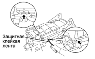
Remove the oil pan by prying between the oil pan and cylinder block with a screwdriver.
Tech Tips
Tape the screwdriver tip before use.
Note
Be careful not to damage the contact surfaces of the cylinder block and oil pan.
-
Remove the O-ring.
-
-
REMOVE CRANKSHAFT POSITION SENSOR
-
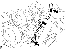
Disconnect the sensor connector.
-
Disconnect the connector from the connector bracket.
-
Detach the harness clamp.
-
Remove the bolt and sensor.
-
-
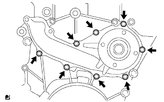
REMOVE TIMING CHAIN COVER (OIL PUMP BODY)
-
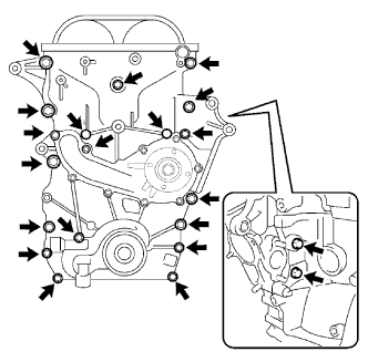
Remove the 19 bolts and 2 nuts shown in the illustration.
-
Remove the timing chain cover by prying between the timing chain cover and cylinder head or cylinder block with a screwdriver.
Tech Tips
Tape the screwdriver tip before use.
Note
Be careful not to damage the contact surfaces of the cylinder head, cylinder block and timing chain cover.
-
Remove the 3 O-rings.
-
Using a 10 mm socket hexagon wrench, remove the timing gear case plug.
-
-
REMOVE WATER PUMP
-
Remove the 8 bolts, water pump and gasket.
-
-
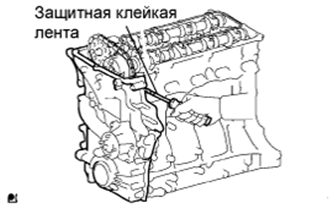
REMOVE TIMING CHAIN COVER OIL SEAL
-
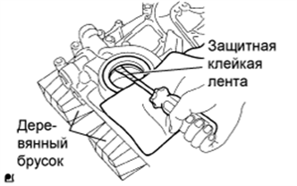
Поместите крышку цепного привода газораспределительного механизма на деревянные бруски.
-
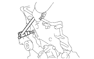
Обернув конец отвертки изолентой, снимите сальник.
-
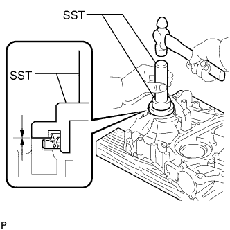
При помощи SST и молотка запрессуйте новый сальник так, чтобы его поверхность была заподлицо с краем крышки цепного привода газораспределительного механизма.
- SST
- 09223-75010
- 09950-70010 ( 09951-07150 )
Note
-
Не допускайте попадания на кромку посторонних материалов.
-
Не стучите по сальнику, направляя удары под углом.
Tech Tips
При установке шкива коленчатого вала проверьте форму шкива. Пригодный шкив имеет канавку (см. стр. Click here).
-
Нанесите тонкий слой универсальной консистентной смазки на кромку нового сальника.
-