SFI SYSTEM, Diagnostic DTC:P104A
| DTC Code | DTC Name |
|---|---|
| P104A | VALVEMATIC SDOWN Circuit |
DESCRIPTION
The ECM turns the power supply to the continuously variable valve lift controller assembly on/off. Normally, when the ignition switch is ON, +B voltage is constantly supplied to the continuously variable valve lift controller assembly. However, when a malfunction is detected in the VALVEMATIC system, the ECM turns the power supply to the continuously variable valve lift controller assembly off. The power supply is turned on/off through the shutdown (SDOWN) signal line between the ECM and continuously variable valve lift controller assembly. When the ignition switch is turned to ON, the ECM turns the shutdown (SDOWN) signal on (Hi) which turns the continuously variable valve lift controller assembly power on. Also, when the ignition switch is off or during fail-safe mode, the shutdown (SDOWN) signal is turned off (Lo) which turns the continuously variable valve lift controller assembly power off.
The ECM electronically monitors whether on/off switching is actually being performed in the ECM output circuit.
DTC No. |
DTC Detection Condition |
Trouble Area |
|---|---|---|
P104A |
The shutdown (SDOWN) signal line has an open circuit, or a short circuit to +B or ground (1 trip detection logic).
|
|
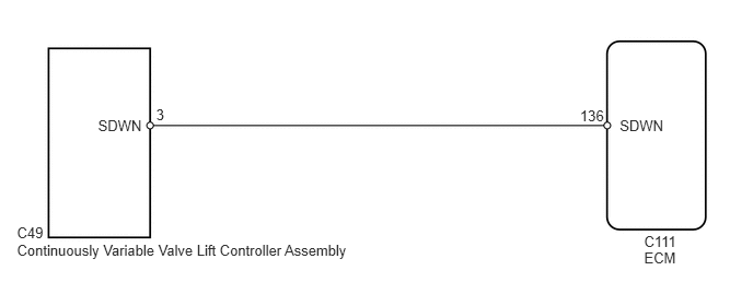
WIRING DIAGRAM
CAUTION / NOTICE / HINT
When one of the following DTCs is output and the MIL is illuminated, actuator position learning is performed during the next trip. After the system returns to normal, actuator position learning is performed during the next trip and the MIL remains illuminated until learning is complete.
Actuator position learning is performed when these DTCs are output. |
|---|
P1049, P104A, P1055, P2646, P2647, P2648, P2649, P264A, U011B |
After performing repairs, perform the following procedures and check that DTCs are not output again.
Connect the GTS to the DLC3.
Turn the ignition switch to ON.
Turn the GTS on.
Clear the DTCs (Click here).
Turn the ignition switch off.
Turn the ignition switch to ON and wait 5 seconds.
Turn the ignition switch off and wait 10 seconds.
Turn the ignition switch to ON.
Enter the following menus: Powertrain / Engine and ECT / Trouble Codes.
Read the DTCs.
After using the GTS to perform minimum valve lift learning, keep the engine idling for 30 seconds to complete learning. Otherwise, the VALVEMATIC system may not operate normally, causing poor acceleration, etc.
PROCEDURE
CHECK ANY OTHER DTCS OUTPUT
Connect the GTS to the DLC3.
Turn the ignition switch to ON.
Turn the GTS on.
Enter the following menus: Powertrain / Engine and ECT / Trouble Codes.
Read the DTC.
Table 1. Result Result
Proceed to
DTC P104A is output
A
DTC P1049 is output at same time as DTC P104A
B
CHECK HARNESS AND CONNECTOR (CONTINUOUSLY VARIABLE VALVE LIFT CONTROLLER ASSEMBLY - ECM)
Disconnect the continuously variable valve lift controller assembly connector.
Disconnect the ECM connector.
Measure the resistance according to the value(s) in the table below.
Standard Resistance (Check for Open)
Tester Connection
Condition
Specified Condition
C111-136 (SDWN) - C49-3 (SDWN)
Ignition switch off
Below 1 Ω
Standard Resistance (Check for Short)
Tester Connection
Condition
Specified Condition
C111-136 (SDWN) or C49-3 (SDWN) - Body ground
Ignition switch off
10 kΩ or higher
Reconnect the continuously variable valve lift controller assembly connector.
Reconnect the ECM connector.
REPAIR OR REPLACE HARNESS OR CONNECTOR (CONTINUOUSLY VARIABLE VALVE LIFT CONTROLLER ASSEMBLY - ECM)