POWER MIRROR CONTROL SYSTEM INSPECTION
-
INSPECT OUTER MIRROR SWITCH ASSEMBLY (w/o Retract Mirror)
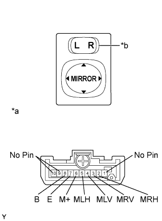
Text in Illustration *a Component without harness connected
(Outer Mirror Switch Assembly)
*b Select switch *c Retract Switch
-
Inspect the outer mirror switch assembly.
-
Select "L" on the select switch.
-
Measure the resistance according to the value(s) in the table below.
Standard Resistance Tester Connection Switch Condition Specified Condition 4 (MLV) - 8 B
6 (M+) - 7 E
UP Pressed Below 1 Ω Not pressed 10 kΩ or higher 4 (MLV) - 7 E
6 (M+) - 8 B
DOWN Pressed Below 1 Ω Not pressed 10 kΩ or higher 5 (MLH) - 8 B
6 (M+) - 7 E
LEFT Pressed Below 1 Ω Not pressed 10 kΩ or higher 5 (MLH) - 7 E
6 (M+) - 8 B
RIGHT Pressed Below 1 Ω Not pressed 10 kΩ or higher If the result is not as specified, replace the outer mirror switch assembly.
-
Select "R" on the select switch.
-
Measure the resistance according to the value(s) in the table below.
Standard Resistance Tester Connection Switch Condition Specified Condition 3 (MRV) - 8 B
6 (M+) - 7 E
UP Pressed Below 1 Ω Not pressed 10 kΩ or higher 3 (MRV) - 7 E
6 (M+) - 8 B
DOWN Pressed Below 1 Ω Not pressed 10 kΩ or higher 2 (MRH) - 8 B
6 (M+) - 7 E
LEFT Pressed Below 1 Ω Not pressed 10 kΩ or higher 2 (MRH) - 7 E
6 (M+) - 8 B
RIGHT Pressed Below 1 Ω Not pressed 10 kΩ or higher If the result is not as specified, replace the outer mirror switch assembly.
-
-
-
INSPECT OUTER MIRROR SWITCH ASSEMBLY (w/ Retract Mirror)
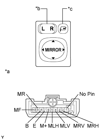
Text in Illustration *a Component without harness connected
(Outer Mirror Switch Assembly)
*b Select switch *c Retract Switch
-
Inspect the outer mirror switch.
-
Select "L" on the select switch.
-
Measure the resistance according to the value(s) in the table below.
Standard Resistance Tester Connection Switch Condition Specified Condition 4 (MLV) - 8 B
6 (M+) - 7 E
UP Pressed Below 1 Ω Not pressed 10 kΩ or higher 4 (MLV) - 7 E
6 (M+) - 8 B
DOWN Pressed Below 1 Ω Not pressed 10 kΩ or higher 5 (MLH) - 8 B
6 (M+) - 7 E
LEFT Pressed Below 1 Ω Not pressed 10 kΩ or higher 5 (MLH) - 7 E
6 (M+) - 8 B
RIGHT Pressed Below 1 Ω Not pressed 10 kΩ or higher If the result is not as specified, replace the outer mirror switch assembly.
-
Select "R" on the select switch.
-
Measure the resistance according to the value(s) in the table below.
Standard Resistance Tester Connection Switch Condition Specified Condition 3 (MRV) - 8 B
6 (M+) - 7 E
UP Pressed Below 1 Ω Not pressed 10 kΩ or higher 3 (MRV) - 7 E
6 (M+) - 8 B
DOWN Pressed Below 1 Ω Not pressed 10 kΩ or higher 2 (MRH) - 8 B
6 (M+) - 7 E
LEFT Pressed Below 1 Ω Not pressed 10 kΩ or higher 2 (MRH) - 7 E
6 (M+) - 8 B
RIGHT Pressed Below 1 Ω Not pressed 10 kΩ or higher If the result is not as specified, replace the outer mirror switch assembly.
-
-
Inspect the retract switch.
-
Measure the resistance according to the value(s) in the table below.
Standard Resistance Tester Connection Switch Condition Specified Condition 7 E - 10 (MF)
8 B - 9 (MR)
Pushed in Below 1 Ω 7 E - 9 (MR)
8 B - 10 (MF)
Not pushed in Below 1 Ω If the result is not as specified, replace the outer mirror switch assembly.
-
-
-
INSPECT OUTER REAR VIEW MIRROR ASSEMBLY LH
-
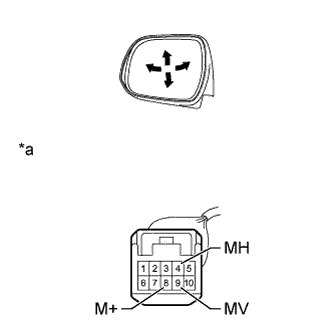
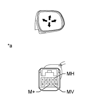
Text in Illustration *a Component without harness connected
(Outer Rear View Mirror Assembly LH)
Disconnect the mirror connector.
-
Apply battery voltage and check operation of the mirror.
OK Measurement Condition Specified Condition Battery positive (+) →Terminal 9 (MV)
Battery negative (-) → Terminal 8 (M+)
Turns upward Battery positive (+) → Terminal 8 (M+)
Battery negative (-) → Terminal 9 (MV)
Turns downward Battery positive (+) → Terminal 4 (MH)
Battery negative (-) → Terminal 8 (M+)
Turns left Battery positive (+) → Terminal 8 (M+)
Battery negative (-) → Terminal 4 (MH)
Turns right If the result is not as specified, replace the outer rear view mirror assembly LH.
-
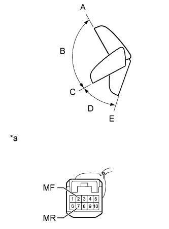
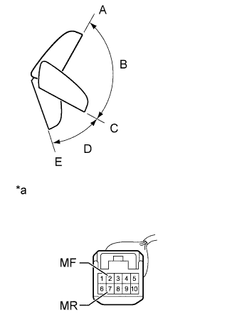
Text in Illustration *a Component without harness connected
(Outer Rear View Mirror Assembly LH)
w/ Retract Mirror:
-
For each position: Disconnect the battery, set the mirror position by hand, connect the battery, and check the retractable mirror movement.
OK Measurement Condition Mirror Position Specified Condition Battery positive (+) → Terminal 7 (MR)
Battery negative (-) → Terminal 2 (MF)
Forward position A Moves from A to retracted position E Battery negative (-) → Terminal 7 (MR)
Battery positive (+) → Terminal 2 (MF)
Forward position A Does not move Battery positive (+) → Terminal 7 (MR)
Battery negative (-) → Terminal 2 (MF)
Position between forward position A and driving position C Moves from B to retracted position E Battery negative (-) → Terminal 7 (MR)
Battery positive (+) → Terminal 2 (MF)
Position between forward position A and driving position C Moves from B to retracted position A Battery positive (+) → Terminal 7 (MR)
Battery negative (-) → Terminal 2 (MF)
Driving position C Moves from C to retracted position E Battery negative (-) → Terminal 7 (MR)
Battery positive (+) → Terminal 2 (MF)
Driving position C Does not move Battery positive (+) → Terminal 7 (MR)
Battery negative (-) → Terminal 2 (MF)
Position between driving position C and retracted position E Moves from D to retracted position E Battery negative (-) → Terminal 7 (MR)
Battery positive (+) → Terminal 2 (MF)
Position between driving position C and retracted position E Moves from D to retracted position C Battery positive (+) → Terminal 7 (MR)
Battery negative (-) → Terminal 2 (MF)
Retracted position E Does not move Battery negative (-) → Terminal 7 (MR)
Battery positive (+) → Terminal 2 (MF)
Retracted position E Moves from E to driving position C Note
-
Disconnect and reconnect the battery between each mirror position check.
-
Do not apply battery voltage when moving the mirror by hand into each mirror position.
If the result is not as specified, replace the outer rear view mirror assembly LH.
-
-
-
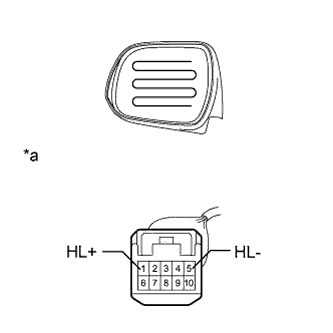
Text in Illustration *a Component without harness connected
(Outer Rear View Mirror Assembly LH)
w/ Mirror Heater:
Check the mirror heater.
-
Measure the resistance according to the value(s) in the table below.
Standard resistance Tester Connection Condition Specified Condition 1 (HL+) - 5 (HL-) 25°C (75°F) 4 to 12 Ω If the result is not as specified, replace the outer rear view mirror assembly LH.
-
Apply battery voltage and check the operation of the mirror heater.
OK Measurement Condition Specified Condition Battery positive (+) → Terminal 1 (HL+)
Battery negative (-) → Terminal 5 (HL-)
Mirror becomes warm Tech Tips
It will take a short time for the mirror to become warm.
If the result is not as specified, replace the outer rear view mirror assembly LH.
-
-
w/ side turn signal light:
-
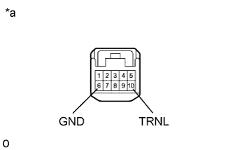
Text in Illustration *a Component without harness connected
(Outer Rear View Mirror Assembly LH)
Check the side turn signal light.
Apply battery voltage to the terminals of the connector, and check the illumination condition.
OK Tester Connection Specified Condition Battery positive (+) → Terminal 10 (TRNL)
Battery negative (-) → Terminal 6 (GND)
Side turn light illuminates If the result is not as specified, replace the side turn signal light assembly LH Click here.
-
-
-
INSPECT OUTER REAR VIEW MIRROR ASSEMBLY RH
-
Text in Illustration *a Component without harness connected
(Outer Rear View Mirror Assembly RH)
Disconnect the mirror connector.
-
Apply battery voltage and check operation of the mirror.
OK Measurement Condition Specified Condition Battery positive (+) →Terminal 9 (MV)
Battery negative (-) → Terminal 8 (M+)
Turns upward Battery positive (+) → Terminal 8 (M+)
Battery negative (-) → Terminal 9 (MV)
Turns downward Battery positive (+) → Terminal 4 (MH)
Battery negative (-) → Terminal 8 (M+)
Turns left Battery positive (+) → Terminal 8 (M+)
Battery negative (-) → Terminal 4 (MH)
Turns right If the result is not as specified, replace the outer rear view mirror assembly RH.
-
Text in Illustration *a Component without harness connected
(Outer Rear View Mirror Assembly RH)
w/ Retract Mirror:
-
For each position: Disconnect the battery, set the mirror position by hand, connect the battery, and check the retractable mirror movement.
OK Measurement Condition Mirror Position Specified Condition Battery positive (+) → Terminal 7 (MR)
Battery negative (-) → Terminal 2 (MF)
Forward position A Moves from A to retracted position E Battery negative (-) → Terminal 7 (MR)
Battery positive (+) → Terminal 2 (MF)
Forward position A Does not move Battery positive (+) → Terminal 7 (MR)
Battery negative (-) → Terminal 2 (MF)
Position between forward position A and driving position C Moves from B to retracted position E Battery negative (-) → Terminal 7 (MR)
Battery positive (+) → Terminal 2 (MF)
Position between forward position A and driving position C Moves from B to retracted position A Battery positive (+) → Terminal 7 (MR)
Battery negative (-) → Terminal 2 (MF)
Driving position C Moves from C to retracted position E Battery negative (-) → Terminal 7 (MR)
Battery positive (+) → Terminal 2 (MF)
Driving position C Does not move Battery positive (+) → Terminal 7 (MR)
Battery negative (-) → Terminal 2 (MF)
Position between driving position C and retracted position E Moves from D to retracted position E Battery negative (-) → Terminal 7 (MR)
Battery positive (+) → Terminal 2 (MF)
Position between driving position C and retracted position E Moves from D to retracted position C Battery positive (+) → Terminal 7 (MR)
Battery negative (-) → Terminal 2 (MF)
Retracted position E Does not move Battery negative (-) → Terminal 7 (MR)
Battery positive (+) → Terminal 2 (MF)
Retracted position E Moves from E to driving position C Note
-
Disconnect and reconnect the battery between each mirror position check.
-
Do not apply battery voltage when moving the mirror by hand into each mirror position.
If the result is not as specified, replace the outer rear view mirror assembly RH.
-
-
-
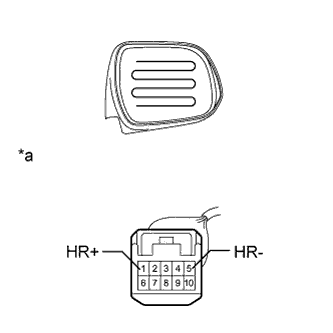
Text in Illustration *a Component without harness connected
(Outer Rear View Mirror Assembly RH)
w/ Mirror Heater:
Check the mirror heater.
-
Measure the resistance according to the value(s) in the table below.
Standard resistance Tester Connection Condition Specified Condition 1 (HR+) - 5 (HR-) 25°C (75°F) 4 to 12 Ω If the result is not as specified, replace the outer rear view mirror assembly RH.
-
Apply battery voltage and check the operation of the mirror heater.
OK Measurement Condition Specified Condition Battery positive (+) → Terminal 1 (HR+)
Battery negative (-) → Terminal 5 (HR-)
Mirror becomes warm Tech Tips
It will take a short time for the mirror to become warm.
If the result is not as specified, replace the outer rear view mirror assembly RH.
-
-
w/ side turn signal light:
-
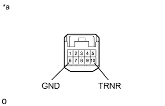
Text in Illustration *a Component without harness connected
(Outer Rear View Mirror Assembly LH)
Check the side turn signal light.
Apply battery voltage to the terminals of the connector, and check the illumination condition.
OK Tester Connection Specified Condition Battery positive (+) → Terminal 10 (TRNR)
Battery negative (-) → Terminal 6 (GND)
Side turn light illuminates If the result is not as specified, check the side turn signal light assembly RH Click here.
-
-