BRAKE BOOSTER(for RHD) REMOVAL
PROCEDURE
PRECAUTION
Note:After turning the power switch off, waiting time may be required before disconnecting the cable from the negative (-) auxiliary battery terminal. Therefore, make sure to read the disconnecting the cable from the negative (-) auxiliary battery terminal notices before proceeding with work.
DISABLE BRAKE CONTROL
REMOVE WINDSHIELD WIPER MOTOR ASSEMBLY
REMOVE OUTER COWL TOP PANEL SUB-ASSEMBLY
REMOVE COWL BODY MOUNTING REINFORCEMENT RH
-
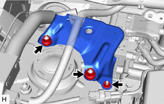
Remove the 3 nuts and cowl body mounting reinforcement RH.
-
DRAIN BRAKE FLUID
Note:Wash off brake fluid immediately if it comes in contact with any painted surface.
REMOVE NO. 1 INSTRUMENT PANEL UNDER COVER SUB-ASSEMBLY
REMOVE PUSH ROD PIN
DISCONNECT BRAKE MASTER CYLINDER RESERVOIR ASSEMBLY
Disconnect the brake fluid level warning switch connector from the brake master cylinder reservoir assembly.
-
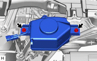
Remove the 2 bolts and disconnect the brake master cylinder reservoir assembly with reservoir bracket.
DISCONNECT NO. 2 RESERVOIR HOSE
-
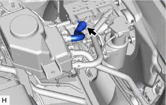
Slide the clip and disconnect the No. 2 reservoir hose from the brake booster with master cylinder assembly.
-
DISCONNECT NO. 1 RESERVOIR HOSE
-
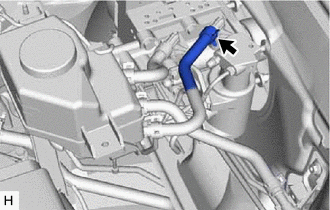
Slide the clip and disconnect the No. 1 reservoir hose from the brake booster with master cylinder assembly.
-
DISCONNECT NO. 2 BRAKE ACTUATOR HOSE
-
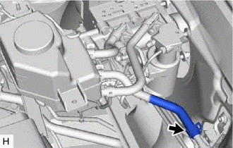
Slide the clip and disconnect the No. 2 brake actuator hose from the No. 1 brake actuator tube.
-
REMOVE BRAKE MASTER CYLINDER RESERVOIR ASSEMBLY
REMOVE RESERVOIR BRACKET
-
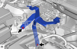
Remove the 2 bolts and reservoir bracket.
-
REMOVE BRAKE BOOSTER WITH MASTER CYLINDER ASSEMBLY
-
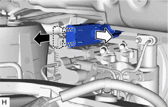

Release the lock lever

Disconnect the connector
Release the lock lever and disconnect the connector from the brake booster with master cylinder assembly.
Note:Be careful not to allow the brake fluid to enter the removed connector.
-
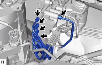
Using a union nut wrench, disconnect the 5 brake tubes from the brake booster with master cylinder assembly.
-
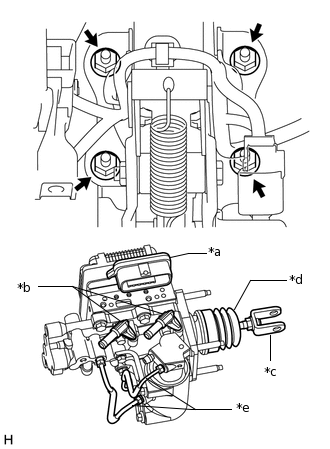
*a
Connector Portion
*b
Union
*c
Push Rod Clevis
*d
Boot
*e
Front No. 2 Brake Tube
Remove the 4 nuts and brake booster with master cylinder assembly.
Note:Do not kink or damage the brake tubes.
Do not carry the brake booster with master cylinder assembly by the portion shown in bold in the illustration.
-
REMOVE BRAKE BOOSTER GASKET