ECD SYSTEM(w/ Glow Plug Controller), Diagnostic DTC:P1603
| DTC Code | DTC Name |
|---|---|
| P1603 | Engine Stall History |
DESCRIPTION
When the fuel pressure in the common rail drops below the threshold and the engine stalls, this DTC is stored.
It is necessary to check if the vehicle has run out of fuel before performing troubleshooting, as this DTC is also stored when the engine stalls due to running out of fuel.
DTC No. |
Detection Item |
DTC Detection Condition |
Trouble Area |
MIL |
Memory |
|---|---|---|---|---|---|
P1603 |
Engine Stall History |
While the engine running, common rail pressure drops below the low level threshold (less than 12000 kPa) and the engine stalls (1 trip detection logic) |
|
- |
DTC stored |
DTC No. |
DTC Detection Drive Pattern |
|---|---|
P1603 |
Engine running at idle or higher speed for more than 1 minute |
DTC No. |
Data List |
|---|---|
P1603 |
|
CAUTION / NOTICE / HINT
In order to obtain stable idling, glow system operation, fuel system operation and compression sufficient to maintain the target idling speed are necessary.
Glow system
The following malfunctions may be present in the glow system.
Engine coolant temperature sensor malfunction.
Glow plug assembly malfunction.
Glow plug relay assembly malfunction.
Fuel system
The following malfunctions may be present in the fuel system.
Fuel leakage.
Problem with injector assemblies.
Problem with supply pump assembly.
Air in fuel line.
Fuel pipes clogged.
Fuel filter clogged.
Engine assembly
The following malfunctions may be present in the engine assembly.
Insufficient compression.
In contrast to normal malfunction diagnosis for components, circuits and systems, DTC P1603 is used to determine the malfunctioning area from the problem symptoms and freeze frame data when the user mentions problems such as engine stall.
As this DTC can be stored as a result of certain user actions, even if this DTC are output, if the customer makes no mention of problems, clear this DTC without performing any troubleshooting and return the vehicle to the customer.
If any other DTCs are output, perform troubleshooting for those DTCs first.
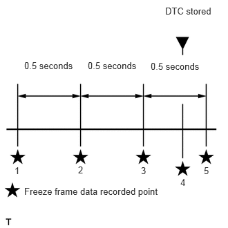
Read freeze frame data using the GTS. Freeze frame data records the engine condition when malfunctions are detected. When troubleshooting, freeze frame data can help determine if the vehicle was moving or stationary, if the engine was warmed up or not, and other data from the time the malfunction occurred.
When confirming the freeze frame data, be sure to check all 5 sets of freeze frame data.
The fourth set of freeze frame data is the data recorded when then the DTC is stored.
PROCEDURE
READ OUTPUT DTC (RECORD STORED DTC AND FREEZE FRAME DATA (PROCEDURE 1))
Connect the GTS to the DLC3.
Turn the ignition switch to ON and turn the GTS on.
Enter the following menus: Powertrain / Engine and ECT / Trouble Codes.
Powertrain > Engine and ECT > Trouble Codes
Record the stored DTCs and freeze frame data.
Tip:This freeze frame data shows the actual engine conditions when engine stall trouble occurred.
Result
Proceed to
NEXT
CHECK ANY OTHER DTCS OUTPUT (IN ADDITION TO DTC P1603)
Connect the GTS to the DLC3.
Turn the ignition switch to ON and turn the GTS on.
Enter the following menus: Powertrain / Engine and ECT / Trouble Codes.
Read the DTCs.
Powertrain > Engine and ECT > Trouble Codes
Result
Result
Proceed to
DTC P1603 is output
A
DTC P1603 and other DTCs are output
B
Tip:If any DTCs other than DTC P1603 are output, troubleshoot those DTCs first.
DETERMINE CAUSE OF PROBLEM (CHECK FREEZE FRAME DATA)
Determine the cause of the problem based on the freeze frame data recorded in Procedure 1 and the Data List.
Table 3. Battery Voltage Judgment of Data List Values
Problem Cause
Normal Condition
Diagnosis Note
"Battery Voltage" in freeze frame data is below 7 V
Engine starting trouble may have occurred because battery is fully depleted
During cranking: 7 V or higher
The battery may be fully depleted or the battery terminals may be loose.
"Battery Voltage" in Data List is below 7 V when cranking engine
Table 4. Common Rail Pressure Judgment of Data List Values
Problem Cause
Normal Condition
Diagnosis Note
"Common Rail Pressure" in freeze frame data is below 1000 kPa
Problem supplying fuel to supply pump assembly (low pressure side)
Ran out of fuel, air in fuel, fuel frozen (in this case, values of "Fuel Temperature" and "Coolant Temp" in freeze frame data are low)
Fuel filter clog, fuel line clog (low pressure side) or fuel leak
Feed pump (in supply pump assembly) malfunctioning
When in a stable condition such as when idling, the fuel pressure is within +/-10000 kPa of the target fuel pressure
Disconnect the inlet hose from the supply pump assembly (low pressure side), operate the hand pump and check that fuel is being supplied.
"Common Rail Pressure" in Data List is below 1000 kPa 2 seconds after engine cranking is started
"Common Rail Pressure" in freeze frame data is below 20000 kPa
Problem supplying fuel to supply pump assembly (low pressure side) or problem on high pressure side
Supply pump assembly (suction control valve operation malfunction)
Common rail assembly
Injector assembly (if glow plug is covered with fuel when removed, injector of corresponding cylinder may be stuck open)
Fuel line clog (high pressure side), fuel leak
When in stable condition such as when idling, fuel pressure is within +/-10000 kPa of target fuel pressure
For startup at least 20000 kPa of fuel pressure is needed (Take care as there is a response lag when the pressure rises)
If "Common Rail Pressure" is 15000 kPa or less, fuel injection control is stopped.
After cranking is started, "Common Rail Pressure" in Data List increases to 20000 kPa or higher and then decreases to below 15000 kPa
"Common Rail Pressure" in freeze frame data or Data List changes within range of 40000 to 45000 kPa
Injector assembly (fuel injection problem caused by air in injector)
Problem with injection system
When in a stable condition such as when idling, the fuel pressure is within +/-10000 kPa of the target fuel pressure
If there is air in the injectors of all cylinders, fuel cannot be injected.
If there is an injection system problem related to 2 or more cylinders, fuel delivery and injection control are stopped.
When the EDU circuit (built into ECM) has a malfunction, the ECM cannot perform diagnosis of malfunctions and DTCs are not stored as voltage is unstable during cranking. Also, an excess amount of fuel is supplied by the supply pump assembly and "Common Rail Pressure" becomes larger than "Target Common Rail Pressure" as fuel injection cannot be performed, even though a fuel injection signal is output, due to a failure to detect malfunctions at engine start.
Table 5. Injection Feedback Val #1 (to #4) Judgment of Data List Values
Problem Cause
Normal Condition
Diagnosis Note
"Injection Feedback Val #1 (to #4)" in freeze frame data is not between -2.0 and 2.0 mm3/st
Injector malfunction or compression problem
-2.0 to 2.0 mm3/st
If a injector assembly is malfunctioning, even though the engine starts, idling is rough.
"Injection Feedback Val #1 (to #4)" in Data List is not between -2.0 and 2.0 mm3/st when idling
Table 6. Injection Volume Judgment of Data List Values
Problem Cause
Normal Condition
Diagnosis Note
"Injection Volume" in Data List is 8 mm3/st or less and "Injection Feedback Val #1 (to #4)" is within range of +/-2 mm3/st when idling after warming up the engine
Injectors of all cylinders are malfunctioning
-
-
Result
Proceed to
NEXT