FRONT DOOR REASSEMBLY
CAUTION / NOTICE / HINT
Use the same procedure for the RH side and LH side.
The following procedure is for the LH side.
PROCEDURE
PRECAUTION
Note:After turning the ignition switch off, waiting time may be required before disconnecting the cable from the negative (-) battery terminal. Therefore, make sure to read the disconnecting the cable from the negative (-) battery terminal notices before proceeding with work.
REPAIR INSTRUCTION (w/ Black Out Tape)
INSTALL NO. 1 BLACK OUT TAPE (w/ Black Out Tape)
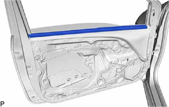
INSTALL FRONT DOOR GLASS OUTER WEATHERSTRIP
INSTALL NO. 2 FRONT DOOR STIFFENER CUSHION
for 3 Door:
Clean the front door panel.
Remove the release paper from a new No. 2 front door stiffener cushion.
Tip:After removing the release paper, keep the exposed adhesive free from foreign matter.
-

Double-sided Tape
Engage the 2 guides.
Install the No. 2 front door stiffener cushion with the 2 bolts.
7.8 N*m
80 kgf*cm
69 in.*lbf
Press the double-sided tape area of the No. 2 front door stiffener cushion for 3 seconds or more.
for 5 Door:
Clean the front door panel.
Remove the release paper from a new No. 2 front door stiffener cushion.
Tip:After removing the release paper, keep the exposed adhesive free from foreign matter.
-
Double-sided Tape
Engage the 2 guides.
Install the No. 2 front door stiffener cushion with the 2 bolts.
7.8 N*m
80 kgf*cm
69 in.*lbf
Press the double-sided tape area of the No. 2 front door stiffener cushion for 3 seconds or more.
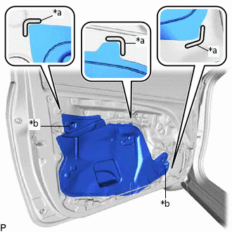
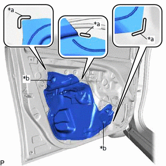
INSTALL FRONT DOOR PANEL CUSHION
-
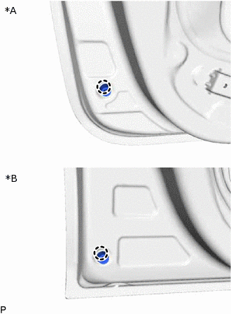
*A
for 3 Door
*B
for 5 Door
Engage the claw to install a new front door panel cushion.
-
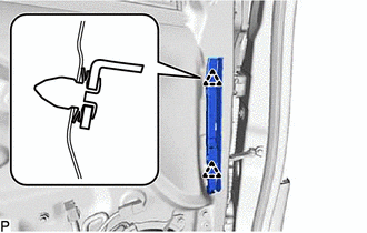
INSTALL FRONT DOOR DUST PROOF SEAL
-
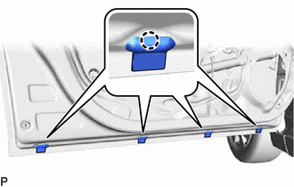
Engage the 4 claws to install 4 new front door dust proof seals.
-
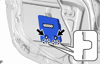
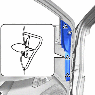
INSTALL SIDE AIRBAG SENSOR ASSEMBLY (for 3 Door)
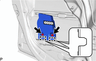
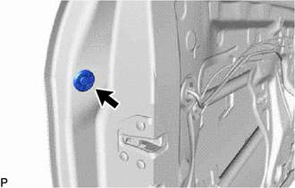
INSTALL FRONT DOOR CHECK ASSEMBLY
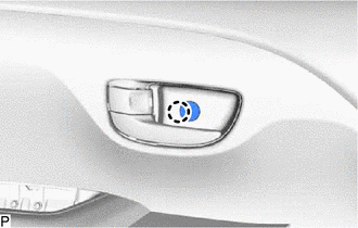
Apply MP grease to the sliding areas of the front door check assembly.
Clean the bolt hole on the vehicle body.
Clean the bolt threads of the bolt (A).
Apply adhesive to the threads of the bolt (A).
Adhesive
Toyota Genuine Adhesive 1324, Three Bond 1324 or equivalent
-
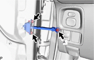
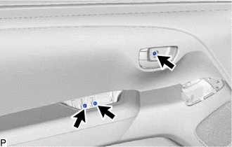
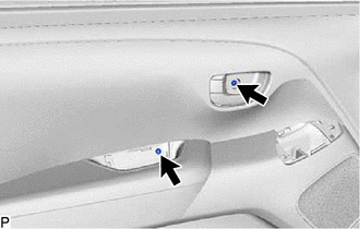
Install the front door check assembly with the 3 bolts.
Bolt (A)
30 N*m
306 kgf*cm
22 ft.*lbf
Bolt (B)
8.0 N*m
82 kgf*cm
71 in.*lbf
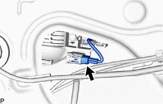
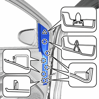
INSTALL FRONT DOOR LOCK OPEN ROD
-
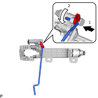
Install the front door lock open rod as indicated by the arrows, in the order shown in the illustration.
-
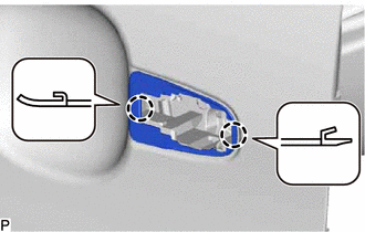
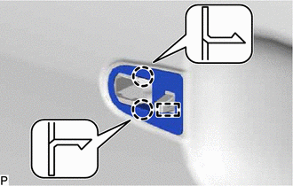
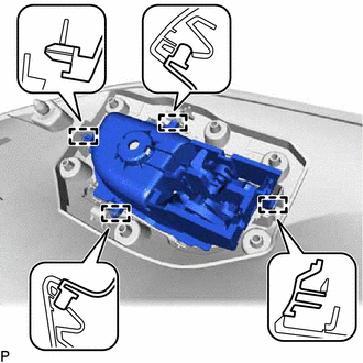
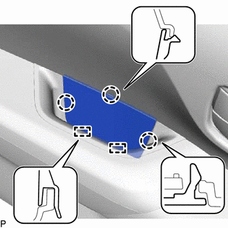
INSTALL FRONT DOOR OUTSIDE HANDLE FRAME SUB-ASSEMBLY
Apply MP grease to the sliding parts on the front door outside handle frame sub-assembly.
w/ Entry and Start System:
-
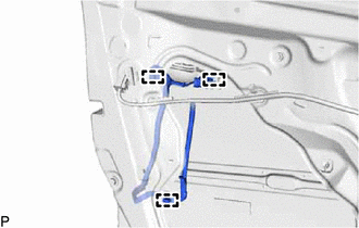
Engage the 3 clamps.
-
-
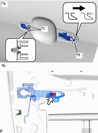
*a
Outside
*b
Inside
*c
Claw (A)
*d
Claw (B)
Engage the claw (B) as shown in the illustration.
Engage the 2 claws (A).
Using a T30 "TORX" socket wrench, install the front door outside handle frame sub-assembly with the screw.
4.0 N*m
41 kgf*cm
35 in.*lbf
INSTALL FRONT DOOR LOCK ASSEMBLY
INSTALL FRONT DOOR REAR OUTSIDE HANDLE PAD
-
Engage the 2 claws to install the front door rear outside handle pad.
-
INSTALL FRONT DOOR FRONT OUTSIDE HANDLE PAD
-
Engage the 2 claws and guide to install the front door front outside handle pad.
-
INSTALL FRONT DOOR OUTSIDE HANDLE ASSEMBLY
-
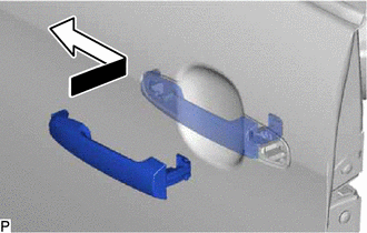
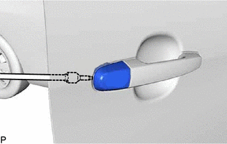
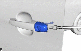
Insert the front end of the front door outside handle assembly into the front door outside handle frame sub-assembly.
Insert the rear end of the front door outside handle assembly into the front door outside handle frame sub-assembly, then slide the front door outside handle assembly toward the front of the vehicle to install it.
w/ Entry and Start System:
-
Connect the connector.
-
-
INSTALL FRONT DOOR OUTSIDE HANDLE COVER (for Driver Side)
-
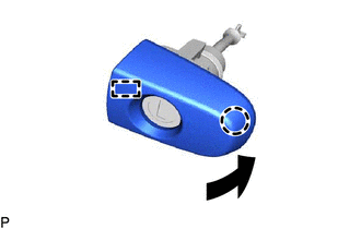
Engage the guide and claw to install the front door outside handle cover to the lock cylinder assembly as shown in the illustration.
-
INSTALL FRONT DOOR OUTSIDE HANDLE COVER (for Front Passenger Side)
w/o Lock Cylinder:
-
Using a T30 "TORX" socket wrench, install the front door outside handle cover with the screw.
4.0 N*m
41 kgf*cm
35 in.*lbf
-
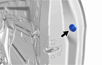
Install the hole plug.
-
w/ Lock Cylinder:
Tip:Use the same procedures as for the driver side.
INSTALL FRONT DOOR OUTSIDE HANDLE COVER WITH LOCK CYLINDER ASSEMBLY (for Driver Side)
-
Using a T30 "TORX" socket wrench, install the front door outside handle cover with lock cylinder assembly with the screw.
4.0 N*m
41 kgf*cm
35 in.*lbf
-
Install the hole plug.
-
INSTALL FRONT DOOR OUTSIDE HANDLE COVER WITH LOCK CYLINDER ASSEMBLY (for Front Passenger Side)
w/ Lock Cylinder:
Tip:Use the same procedures as for the driver side.
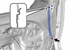
INSTALL FRONT DOOR REAR LOWER FRAME SUB-ASSEMBLY
-
Engage the guide.
Install the front door rear lower frame sub-assembly with the bolt.
7.8 N*m
80 kgf*cm
69 in.*lbf
-
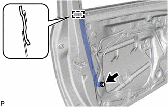
INSTALL FRONT DOOR FRONT LOWER FRAME SUB-ASSEMBLY
-
Engage the guide.
Install the front door front lower frame sub-assembly with the bolt.
7.8 N*m
80 kgf*cm
69 in.*lbf
-
INSTALL FRONT DOOR GLASS RUN
-
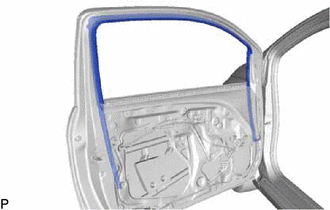
Install the front door glass run.
-
INSTALL FRONT DOOR WINDOW REGULATOR ASSEMBLY (w/o Power Window)
Apply MP grease to the sliding parts of the front door window regulator assembly.
-
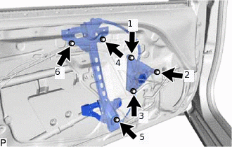
Install the front door window regulator assembly with the 6 bolts.
Tip:Tighten the bolts in the order shown in the illustration.
8.0 N*m
82 kgf*cm
71 in.*lbf
INSTALL FRONT DOOR WINDOW REGULATOR ASSEMBLY (w/ Power Window)
Apply MP grease to the sliding parts of the front door window regulator assembly.
-
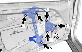
Install the front door window regulator assembly with the 6 bolts.
Tip:Tighten the bolts in the order shown in the illustration.
8.0 N*m
82 kgf*cm
71 in.*lbf
Connect the connector.
INSTALL FRONT DOOR GLASS SUB-ASSEMBLY (w/o Power Window)
Temporarily install the front door window regulator handle assembly and move the front door glass sub-assembly so that the door glass bolts can be seen.
Remove the front door window regulator handle assembly.
-
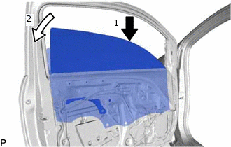
Insert the front door glass sub-assembly into the front door panel along the front door glass run as indicated by the arrows, in the order shown in the illustration.
-
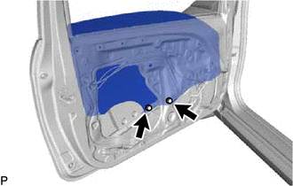
Install the front door glass sub-assembly with the 2 bolts.
8.0 N*m
82 kgf*cm
71 in.*lbf
INSTALL FRONT DOOR GLASS SUB-ASSEMBLY (w/ Power Window)
Connect the cable to the negative (-) battery terminal.
for Driver Side:
Connect the power window regulator master switch assembly and move the front door glass sub-assembly so that the door glass bolts can be seen.
for Front Passenger Side:
Connect the power window regulator switch assembly and move the front door glass sub-assembly so that the door glass bolts can be seen.
Disconnect the cable from the negative (-) battery terminal.
for Driver Side:
Disconnect the power window regulator master switch assembly.
for Front Passenger Side:
Disconnect the power window regulator switch assembly.
-
Insert the front door glass sub-assembly into the front door panel along the front door glass run as indicated by the arrows, in the order shown in the illustration.
-
Install the front door glass sub-assembly with the 2 bolts.
8.0 N*m
82 kgf*cm
71 in.*lbf
INSTALL FRONT DOOR SERVICE HOLE COVER
for 3 Door:
Apply new butyl tape to the front door panel.
-
*a
Reference Point
*b
Protruding Part
Insert the protruding part of a new front door service hole cover into the guide hole of the front door panel.
Install the front door service hole cover according to the reference points on the front door panel.
for 5 Door:
Apply new butyl tape to the front door panel.
-
*a
Reference Point
*b
Protruding Part
Insert the protruding part of a new front door service hole cover into the guide hole of the front door panel.
Install the front door service hole cover according to the reference points on the front door panel.
INSTALL FRONT NO. 1 SPEAKER ASSEMBLY
INSTALL NO. 1 DOOR TRIM BRACKET (w/ Mirror Heater)
-
Engage the 2 clips to install the No. 1 door trim bracket.
-
INSTALL OUTER REAR VIEW MIRROR ASSEMBLY WITH COVER
INSTALL FRONT DOOR INNER GLASS WEATHERSTRIP ASSEMBLY
-
Install the front door inner glass weatherstrip assembly.
-
INSTALL FRONT DOOR INSIDE HANDLE SUB-ASSEMBLY
-
Engage the 4 guides to install the front door inside handle sub-assembly to the front door trim board sub-assembly.
-
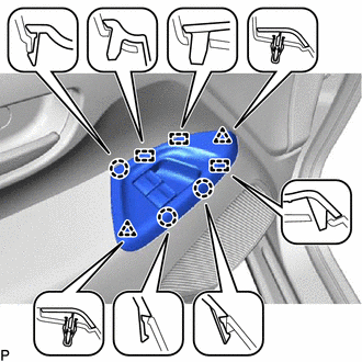
INSTALL FRONT DOOR TRIM BOARD SUB-ASSEMBLY
-
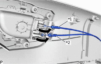
*1
Front Door Inside Locking Cable Assembly
*2
Front Door Lock Remote Control Cable Assembly
Connect the front door lock remote control cable assembly and front door inside locking cable assembly as shown in the illustration.
-
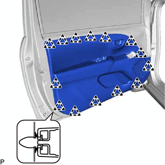
for 3 Door:
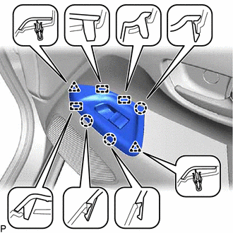
Engage the 14 clips to install the front door trim board sub-assembly.
for 5 Door:
-
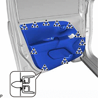
Engage the 11 clips to install the front door trim board sub-assembly.
-
-
for 3 Door:
Install the 3 screws.
for 5 Door:
-
Install the 2 screws.
-
-
Engage the claw and close the cover.
-
INSTALL FRONT DOOR LOWER FRAME BRACKET GARNISH (w/ Mirror Heater)
-
Engage the clip and 7 claws to install the front door lower frame bracket garnish.
-
INSTALL FRONT DOOR LOWER FRAME BRACKET GARNISH (w/o Mirror Heater)
-
Engage the 3 clips to install the front door lower frame bracket garnish.
-
INSTALL FRONT DOOR TRIM COVER
-
Engage the 3 claws and 2 guides to install the front door trim cover.
-
INSTALL FRONT DOOR WINDOW REGULATOR HANDLE ASSEMBLY (w/o Power Window)
Fully close the front door window.
Install the front door window regulator handle shaft snap ring to the front door window regulator handle assembly.
-
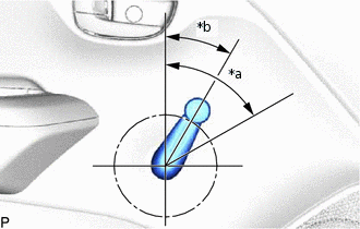
*a
60°
*b
30°
Install the front door window regulator handle assembly with front door window regulator handle shaft snap ring at the angle shown in the illustration.
INSTALL POWER WINDOW REGULATOR MASTER SWITCH ASSEMBLY WITH FRONT DOOR UPPER ARMREST BASE PANEL (for Driver Side with Power Window)
Connect the connector.
-
Engage the 3 guides, 3 claws and 2 clips to install the power window regulator master switch assembly with front door upper armrest base panel.
INSTALL POWER WINDOW REGULATOR SWITCH ASSEMBLY WITH FRONT DOOR UPPER ARMREST BASE PANEL (for Front Passenger Side with Power Window)
Connect the connector.
-
Engage the 3 guides, 3 claws and 2 clips to install the power window regulator switch assembly with front door upper armrest base panel.
CONNECT CABLE TO NEGATIVE BATTERY TERMINAL
Note:When disconnecting the cable, some systems need to be initialized after the cable is reconnected.
Click here
INSPECT POWER WINDOW OPERATION (w/ Power Window)