SFI SYSTEM FREEZE FRAME DATA
DESCRIPTION
The ECM records vehicle and driving condition information as freeze frame data the moment a DTC is stored. When troubleshooting, freeze frame data can be helpful in determining whether the vehicle was moving or stationary, whether the engine was warmed up or not, whether the air fuel ratio was lean or rich, as well as other data recorded at the time of a malfunction.
Tip:If it is impossible to replicate the problem even though a DTC is detected, confirm the freeze frame data.
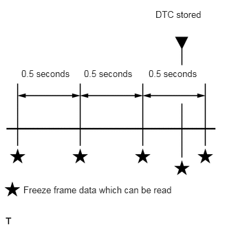
The ECM records engine conditions in the form of freeze frame data every 0.5 seconds. Using the GTS, 5 separate sets of freeze frame data can be checked.
3 data sets before the DTC was stored.
1 data set when the DTC was stored.
1 data set after the DTC was stored.
These data sets can be used to simulate the condition of the vehicle around the time of the occurrence the malfunction. The data may assist in identifying the cause of the malfunction, and judging whether it was temporary or not.
LIST OF FREEZE FRAME DATA
Powertrain > Engine and ECT
Tester Display
Vehicle Speed
Engine Speed
Calculate Load
Vehicle Load
Atmosphere Pressure
MAP
Coolant Temp
Intake Air
Ambient Temperature
Engine Run Time
Initial Engine Coolant Temp
Initial Intake Air Temp
Battery Voltage
Accel Sens. No.1 Volt %
Accel Sens. No.2 Volt %
Throttle Motor DUTY
Throttle Sensor Volt %
Throttle Sensor #2 Volt %
Throttle Sensor Position
Throttle Motor DUTY
Throttle Position
ISC Flow
ISC Feedback Value
ISC Learning Value
Electric Load Feedback Val
Air Conditioner FB Val
PS Feedback Val
Low Revolution Control
Neutral Control
Eng Stall Control FB Flow
Deposit Loss Flow
Injector (Port)
Injection Volum (Cylinder1)
Fuel Pump/Speed Status
Current Fuel Type
EVAP (Purge) VSV
Evap Purge Flow
Purge Density Learn Value
EVAP Purge VSV
Purge Cut VSV Duty
Target Air-Fuel Ratio
A/F Heater Duty B1S1
O2S B1S1
O2S B1S2
O2S Impedance B1S2
O2 Heater B1S1
O2 Heater B1S2
Short FT B1S1
Long FT B1S1
Total FT #1
Fuel System Status #1
Fuel System Status #2
O2FT B1S1
IGN Advance
Knock Feedback Value
Knock Correct Learn Value
Idle Spark Advn Ctrl #1
Idle Spark Advn Ctrl #2
Idle Spark Advn Ctrl #3
Target EGR Position
EGR Step Position
VVT Control Status #1
VVT Advance Fail
Catalyst Temp B1S1
Catalyst Temp B1S2
Starter Signal
Power Steering Signal
Clutch Switch
Stop Light Switch
Shift Indication Enable
A/C Signal
Closed Throttle Position SW
Immobiliser Communication
ASL Switch
TC Terminal
Time after DTC Cleared
Distance from DTC Cleared
Warmup Cycle Cleared DTC
Dist Batt Cable Disconnect
TC and TE1
Total Distance Traveled
Ignition Trig. Count
Cylinder #1 Misfire Count
Cylinder #2 Misfire Count
Cylinder #3 Misfire Count
All Cylinders Misfire Count
Misfire RPM
Engine Speed (Starter Off)
Starter Count
Run Dist of Previous Trip
Engine Starting Time
Previous Trip Coolant Temp
Previous Trip Intake Temp
Engine Oil Temperature
Previous Trip Eng Oil Temp
Ambient Temp for A/C
Previous Trip Ambient Temp
Engine Start Hesitation
Low Rev for Eng Start
Minimum Engine Speed
Fuel Cut Elps Time
Battery Current
Battery Temperature
Alternator Output Duty
Alt Vol - Non Active Test
Alt Vol - Active Test
Brake Boost Pressure Sensor
A/C Magnetic Clutch Relay
Electric Fan Motor
Brake Override System
Electric Cooling Fan High
Electric Cooling Fan Low
Idle Fuel Cut
FC TAU
Immobiliser Fuel Cut
Immobiliser Fuel Cut History
Communication with ECT
Electrical Load Signal 1
Electrical Load Signal 3
Kick Down Switch Status
Shift SW Status (R Range)
MT Down Shift Indication
MT Up Shift Indication
Stop&Start of Eng State
Cancel Switch
SET/COAST Switch
RES/ACC Switch