FRONT EVAPORATOR TEMPERATURE SENSOR INSPECTION
PROCEDURE
INSPECT NO. 1 COOLER THERMISTOR
Measure the resistance according to the value(s) in the table below.
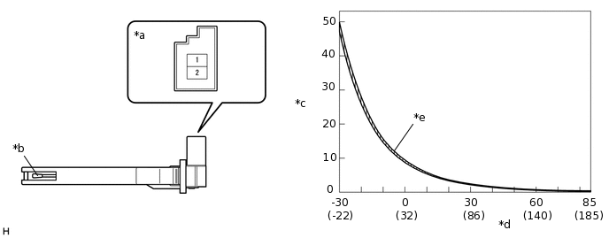
*a
Component without harness connected
(No. 1 Cooler Thermistor)
*b
Sensing Portion
*c
Resistance (kΩ)
*d
Temperature (°C (°F))
*e
Allowable Range
-
-
Standard Resistance
Tester Connection
Condition
Specified Condition
1 (-) - 2 (TE)
-30°C (-22°F)
47.59 to 49.99 kΩ
-25°C (-13°F)
35.12 to 36.76 kΩ
-20°C (-4°F)
26.19 to 27.33 kΩ
-15°C (5°F)
19.71 to 20.50 kΩ
-10°C (14°F)
14.97 to 15.53 kΩ
-5°C (23°F)
11.47 to 11.86 kΩ
0°C (32°F)
8.87 to 9.14 kΩ
5°C (41°F)
6.88 to 7.12 kΩ
10°C (50°F)
5.39 to 5.59 kΩ
15°C (59°F)
4.25 to 4.41 kΩ
20°C (68°F)
3.37 to 3.51 kΩ
25°C (77°F)
2.70 to 2.82 kΩ
30°C (86°F)
2.17 to 2.27 kΩ
35°C (95°F)
1.76 to 1.84 kΩ
40°C (104°F)
1.43 to 1.51 kΩ
45°C (113°F)
1.17 to 1.24 kΩ
50°C (122°F)
0.97 to 1.02 kΩ
55°C (131°F)
0.80 to 0.85 kΩ
60°C (140°F)
0.66 to 0.71 kΩ
65°C (149°F)
0.56 to 0.59 kΩ
70°C (158°F)
0.47 to 0.50 kΩ
75°C (167°F)
0.40 to 0.42 kΩ
80°C (176°F)
0.34 to 0.36 kΩ
85°C (185°F)
0.29 to 0.31 kΩ
Note:Hold the sensor only by its connector. Touching the sensing portion may change the resistance value.
When measuring, the sensor temperature must be the same as the ambient temperature.
Tip:As the temperature increases, the resistance decreases (See the graph).
If the result is not as specified, replace the No. 1 cooler thermistor.