REAR POWER SEAT CONTROL SYSTEM(for Third Row) Back Door Courtesy Switch Circuit
DESCRIPTION
Each fold seat control ECU receives back door courtesy light switch input signal to determine the state of the back door and enable or disable the fold and return functions.
WIRING DIAGRAM
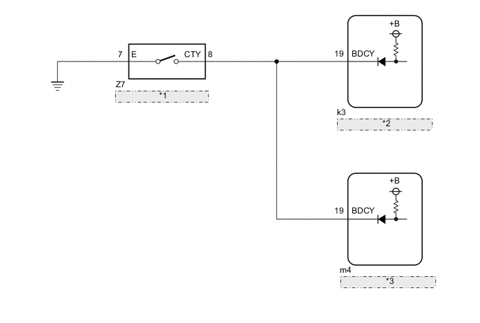
| *1 | Back Door Lock Assembly |
| *2 | Fold Seat Control ECU (RH Seat) |
| *3 | Fold Seat Control ECU (LH Seat) |
CAUTION / NOTICE / HINT
Note
When a fold seat control ECU (RH/LH seat) is replaced, it is necessary to perform initialization.
PROCEDURE
-
CHECK REAR POWER SEAT CONTROL SYSTEM (for Third Row)
-
Check that the rear power seat control system (for Third Row) function operates normally.
Result Result Proceed to Fold/Return functions of both rear No. 2 power seats do not operate normally. A Fold/Return functions of rear No. 2 power seat RH do not operate normally. B Fold/Return functions of rear No. 2 power seat LH do not operate normally. C
B 
CHECK FOLD SEAT CONTROL ECU (RH SEAT) Click here
C
CHECK FOLD SEAT CONTROL ECU (LH SEAT) Click here
A 
-
-
CHECK BACK DOOR EASY CLOSER SYSTEM
-
Check if the back door easy closer system operates normally.
OK Back door easy closer system operates normally. Result Proceed to OK NG
NG 
GO TO LIGHTING SYSTEM (BACK DOOR COURTESY SWITCH CIRCUIT) Click here
OK
-
-
CHECK HARNESS AND CONNECTOR (FOLD SEAT CONTROL ECU (RH/LH SEAT) - BACK DOOR LOCK ASSEMBLY)
-
Disconnect the k3 fold seat control ECU (RH seat) connector.
-
Disconnect the m4 fold seat control ECU (LH seat) connector.
-
Disconnect the Z7 back door lock assembly connector.
-
Measure the resistance according to the value(s) in the table below.
Standard Resistance Tester Connection Condition Specified Condition k3-19 (BDCY) or m4-19 (BDCY) - Z7-8 (CTY) Always Below 1 Ω k3-19 (BDCY), m4-19 (BDCY) or Z7-8 (CTY) - Body ground Always 10 kΩ or higher Result Proceed to OK NG
OK
PROCEED TO NEXT SUSPECTED AREA SHOWN IN PROBLEM SYMPTOMS TABLE Click here
NG
REPAIR OR REPLACE HARNESS OR CONNECTOR
-
-
CHECK FOLD SEAT CONTROL ECU (RH SEAT)
-
Disconnect the m4 fold seat control ECU (LH seat) connector.
-
Disconnect the Z7 back door lock assembly connector.
-
Measure the voltage according to the value(s) in the table below.
Standard Voltage Tester Connection Condition Specified Condition Z7-8 (CTY) - Body ground Always 11 to 14 V Result Proceed to OK NG
OK
PROCEED TO NEXT SUSPECTED AREA SHOWN IN PROBLEM SYMPTOMS TABLE Click here
NG
-
-
CHECK HARNESS AND CONNECTOR (FOLD SEAT CONTROL ECU (RH SEAT) - BACK DOOR LOCK ASSEMBLY)
-
Disconnect the k3 fold seat control ECU (RH seat) connector.
-
Measure the resistance according to the value(s) in the table below.
Standard Resistance Tester Connection Condition Specified Condition k3-19 (BDCY) - Z7-8 (CTY) Always Below 1 Ω Result Proceed to OK NG
OK
REPLACE FOLD SEAT CONTROL ECU (RH SEAT) Click here
NG
REPAIR OR REPLACE HARNESS OR CONNECTOR
-
-
CHECK FOLD SEAT CONTROL ECU (LH SEAT)
-
Disconnect the k3 fold seat control ECU (RH seat) connector.
-
Disconnect the Z7 back door lock assembly connector.
-
Measure the voltage according to the value(s) in the table below.
Standard Voltage Tester Connection Condition Specified Condition Z7-8 (CTY) - Body ground Always 11 to 14 V Result Proceed to OK NG
OK
PROCEED TO NEXT SUSPECTED AREA SHOWN IN PROBLEM SYMPTOMS TABLE Click here
NG
-
-
CHECK HARNESS AND CONNECTOR (FOLD SEAT CONTROL ECU (LH SEAT) - BACK DOOR LOCK ASSEMBLY)
-
Disconnect the m4 fold seat control ECU (LH seat) connector.
-
Measure the resistance according to the value(s) in the table below.
Standard Resistance Tester Connection Condition Specified Condition m4-19 (BDCY) - Z7-8 (CTY) Always Below 1 Ω Result Proceed to OK NG
OK
REPLACE FOLD SEAT SWITCH ASSEMBLY (LH SEAT) Click here
NG
REPAIR OR REPLACE HARNESS OR CONNECTOR
-