ECD SYSTEM(w/ Glow Plug Controller) Rough Idling or Excessive Engine Vibrations
| DTC Code | DTC Name |
|---|---|
| Rough Idling or Excessive Engine Vibrations |
DESCRIPTION
Malfunction Condition |
Main Trouble Area |
Related Trouble Area |
|---|---|---|
|
|
|
Rough idling and excessive engine vibrations are checked in this troubleshooting procedure.
Specified values in the following troubleshooting flowchart are for reference only. Variations in the Data List result values may occur depending on the measuring conditions or the vehicle age. Do not judge the vehicle to be normal even when the Data List values indicate a standard level. Hidden factors of the malfunction are possible.
Check that the vehicle has not been modified in any way prior to the vehicle inspection.
Faults and Symptoms of Common Rail Diesel Components
Engine Control
Table 1. Mass Air Flow Meter Component
Mass air flow meter
Main fault
Decrease in performance (foreign matter is attached)
Symptoms
Lack of power, black smoke
Data List
MAF
Tip:The maximum fuel injection volume is controlled according to the output from the mass air flow meter.
Table 2. Glow System Component
Glow system
Main fault
Open circuit, glow plug relay fault
Symptoms
Difficult to start, rough idle, knocking, white smoke (when cold)
Data List
Check the glow plug indicator light
Diagnostic Point
Try to measure the resistance of the glow plug
Table 3. Engine Component
Engine
Main fault
Loss of compression
Symptoms
Rough idle (lack of power always)
Data List
Engine Speed of Cyl
When cranking during the "Check the Cylinder Compression" Active Test, if there is a high speed cylinder, approx. 100 rpm more than the other cylinders, that cylinder may lose compression.
Injection Feedback Val
"Injection Feedback Val" more than 2.0 mm3/st: Injector breakdown is causing injection volume deviation, or insufficient compression is causing poor combustion.
Diesel Injection
Table 4. Fuel Supply Pump Component
Supply pump assembly
Main fault
-
Symptoms
Difficult to start, engine stalling, rough idle, lack of power
Data List
Common Rail Pressure, Target Common Rail Pressure, Target Pump SCV Current
When in a stable condition such as when idling, the fuel pressure is within +/-10000 kPa of the target fuel pressure.
If the fuel pressure is 20000 kPa below the target pressure then a lack of power will be felt.
If the fuel pressure is below 25000 kPa then idling will be rough.
Tip:The fuel pressure changes at engine starting, but is approx. 25000 kPa at engine start after the engine is warmed up.
When Target Pump SCV Current is 1530 mA or more, the suction control valve has a tendency to become stuck.
Diagnostic Trouble Code
Even if Common Rail Pressure is less than Target Common Rail Pressure, a DTC may not be stored.
Table 5. Fuel Filter Component
Fuel filter
Main fault
Blockage
Symptoms
Difficult to start, engine stalling, rough idle, lack of power
Data List
Common Rail Pressure, Target Common Rail Pressure
When in a stable condition such as when idling, the fuel pressure is within +/-10000 kPa of the target fuel pressure.
If the fuel pressure is 20000 kPa below the target pressure then a lack of power will be felt.
If the fuel pressure is below 25000 kPa then idling will be rough.
Tip:The fuel pressure changes at engine starting, but is approx. 25000 kPa at engine start after the engine is warmed up.
Diagnostic Trouble Code
Even if Common Rail Pressure is less than Target Common Rail Pressure, a DTC may not be stored.
Table 6. Injector Assembly Component
Injector assembly
Main fault
Injection hole blockage
Nozzle needle or valve piston does not move smoothly
Symptoms
Rough idle, lack of power, black smoke, white smoke, knocking
Data List
Injection Feedback Val
"Injection Feedback Val" more than 2.0 mm3/st: Injector assembly breakdown is causing injection volume deviation, or insufficient compression is causing poor combustion.
Table 7. Pressure Control Valve Component
Pressure control valve (common rail assembly)
Main fault
Does not completely close
Symptoms
Difficult to start, engine stall, rough idle, lack of power
Table 8. Fuel Pressure Sensor Component
Fuel pressure sensor (common rail assembly)
Main fault
Open circuit, decrease in performance (foreign matter is attached)
Symptoms
Difficult to start, rough idle, engine stall, lack of power
Data List
Common Rail Pressure, Target Common Rail Pressure
Slowly raise the engine speed from idling to 3000 rpm with the vehicle stopped, and check that Fuel Press follows Target Common Rail Pressure. If the fuel pressure sensor malfunctions, the actual fuel pressure may deviate from the target fuel pressure. (However, the value may not deviate even when a malfunction is present).
Diagnostic Trouble Code
When the fuel pressure sensor has a fault, some DTCs may be stored.
Table 9. Irregular Fuel Component
Irregular fuel
Main fault
-
Symptoms
Difficult to start, rough idle (especially when cold)
Diesel EGR
Table 10. EGR System Component
EGR system
Main fault
Does not move smoothly
Does not close completely
Symptoms
Rough idle
EGR valve stuck closed: Loud turbocharger sound.
EGR valve stuck open: Difficult to start (does not stall), black smoke, lack of power (if there is an excess in the quantity of recirculated exhaust gas and the engine is under heavy load, when the vehicle starts moving, a lack of power will be felt).
Data List
Actual EGR Valve Pos, Target EGR Valve Pos
Generally, Actual EGR Valve Pos = Target EGR Valve Pos +/-5% (fully closed 0%, fully open 100%).
Using EGR valve Active Test, check whether Actual EGR Valve Pos follows Target EGR Valve Pos (the engine coolant temperature and intake air temperature should be considered when a malfunction occurs).
EGR valve is fully closed when the ignition switch is turned to ON (engine stopped).
EGR valve opens to the halfway point at idling after the engine warmed up.
Diesel Throttle
Table 11. Diesel Throttle System Component
Diesel throttle system
Main fault
Stuck, does not move smoothly
Symptoms
Stuck closed: Lack of power, difficult to start, rough idle, engine stall, black smoke. These may occur when stuck almost fully closed.
Stuck open: Turbocharger sound increases. When the engine is stopped, engine vibrations may occur.
Data List
Actual Throttle Position, Target Throttle Position
100%: Fully open
0%: Fully closed
If there is a malfunction of the throttle actuator, compare the target and actual throttle position values for the troubleshooting.
WIRING DIAGRAM
Refer to DTC P0001.
CAUTION / NOTICE / HINT
When cleaning the electric EGR control valve assembly or diesel throttle body assembly, use a piece of cloth soaked with cleaning solvent. Spraying solvent directly onto these parts or soaking the parts in solvent may damage the parts.
When replacing the ECM and/or injector assembly, perform ECM Initialization and Registration.
Before troubleshooting, conduct the following:
(a) Check the fuel quality.
(b) Check the fuel line for air.
(c) Check the fuel system for blockage.
(d) Check the air filter.
(e) Check the engine oil.
(f) Check the engine coolant.
(g) Check the engine idling speed and maximum engine speed.
(h) Check the vacuum pump.
PROCEDURE
CHECK MALFUNCTION CONDITION
Identify when shuddering occurs.
Result
Result
Proceed to
When idling
A
When engaging engine clutch at vehicle start
B
(Clutch system shudders)
B REPAIR OR REPLACE CLUTCH SYSTEM
CHECK HARNESS AND CONNECTOR (IN ENGINE ROOM)
Check the wire harness and connector connections of common rail system components.
OK
The wire harnesses and connectors are connected securely.
Result
Proceed to
OK
NG
NG REPAIR OR REPLACE HARNESS OR CONNECTOR
READ OUTPUT DTC (RELATING TO ENGINE)
Connect the GTS to the DLC3.
Turn the ignition switch to ON and turn the GTS on.
Enter the following menus: Powertrain / Engine and ECT / Trouble Codes.
Read the DTCs.
Powertrain > Engine and ECT > Trouble Codes
Result
Result
Proceed to
DTC is not output
A
Engine related DTCs are output
B
Tip:If DTC P1605 is output, proceed to step 4.
TAKE SNAPSHOT DURING IDLING AND 3000 RPM
Connect the GTS to the DLC3.
Start the engine and allow it to idle until the engine coolant temperature sensor reaches 75°C (167°F) or higher.
Tip:The shift lever should be in neutral and the A/C switch and all accessory switches should be off.
Turn the GTS on.
Enter the following menus: Powertrain / Engine and ECT / Data List / All Data.
Take a snapshot of the following Data List items.
Tip:Check the Data List at idling and at 3000 rpm with no load after the engine is warmed up.
Table 12. Data Condition Idling (Engine Warmed Up, A/C Off, Shift Lever in neutral) Data List
Engine Speed
MAP
MAF
Target Common Rail Pressure
Common Rail Pressure
Target Pump SCV Current
Injection Volume
Target VN Turbo Position
Target EGR Valve Pos
Actual EGR Valve Pos
Target Throttle Position
Actual Throttle Position
Accel Position
Atmosphere Pressure
Coolant Temp
Calculate Load
Pilot 1 Injection Period
Pilot 2 Injection Period
Table 13. Data Condition at 3000 rpm (Engine Warmed Up, A/C Off, Shift Lever in neutral) Data List
Engine Speed
Target Booster Pressure
MAP
MAF
Target Common Rail Pressure
Common Rail Pressure
Target Pump SCV Current
Injection Volume
Target VN Turbo Position
Target EGR Valve Pos
Actual EGR Valve Pos
Target Throttle Position
Actual Throttle Position
Accel Position
Coolant Temp
Calculate Load
Pilot 1 Injection Period
Pilot 2 Injection Period
Result
Proceed to
NEXT
CHECK SNAPSHOT (COMMON RAIL PRESSURE AND TARGET COMMON RAIL PRESSURE)
Check Fuel Press and Target Common Rail Pressure in the snapshot taken when the engine was idling.
Result
Result
Proceed to
Common Rail Pressure is within +/-10000 kPa of Target Common Rail Pressure.
A
Common Rail Pressure is outside range of +/-10000 kPa from Target Common Rail Pressure.
B
B CHECK AND REPLACE FUEL INLET LINEClick here
CHECK SNAPSHOT (TARGET PUMP SCV CURRENT)
Check Target Pump SCV Current in the snapshot taken when the engine was idling and at 3000 rpm with no load.
Result
Result
Proceed to
Target Pump SCV Current is less than 1530 mA
A
Target Pump SCV Current is 1530 mA or more
B
B CHECK HARNESS AND CONNECTOR (SUCTION CONTROL VALVE - ECM)Click here
CHECK INJECTOR COMPENSATION CODE
Read the injector compensation codes.
OK
Compensation codes stored in the ECM match the compensation codes of the installed injector assemblies.
Result
Proceed to
OK
NG
NG PERFORM REGISTRATION AND INITIALIZATIONClick here
CHECK SNAPSHOT (INJECTION FEEDBACK VAL #1 to #4)
Check Injection Feedback Val #1 to #4 and Injection Volume in the snapshot taken after the engine is warmed up and has idled for 1 minute.
Tip:The shift lever should be in neutral and the A/C switch and all accessory switches should be off.
Result
Result
Proceed to
Injection Feedback Val #1 to #4 is within the range of +/-2 mm3/st and Injection Volume is 8 mm3/st or less
A
Injection Feedback Val #1 to #4 is within the range of +/-2 mm3/st and Injection Volume is more than 8 mm3/st
B
*1
Injection Feedback Val #1 to #4 is outside the range of +/-2 mm3/st*2
C
Tip:*1: When this result occurs, usually symptoms may be noticeable, such as difficult starting, rough idling, knocking or black smoke at high common rail pressure.
*2: There may be a malfunction in the corresponding cylinder.
If the value of Injection Volume is more than 8 mm3/st and the value of Injection Feedback Val #1 to #4 is within the threshold, replace the injector assemblies for all cylinders.
In this case, there is a possibility that too much recirculated exhaust gas is entering the engine. Therefore, you should compare the Target EGR Valve Pos with the Actual EGR Valve Pos by entering the following menus using the GTS: Powertrain / Engine and ECT / Data List / Target EGR Valve Pos and Actual EGR Valve Pos.
If the difference between Target EGR Valve Pos and Actual EGR Valve Pos exceeds +/-10%, the EGR system may be malfunctioning.
C PERFORM ACTIVE TEST USING GTS (CONTROL THE SELECT CYLINDER FUEL CUT)Click here
B REPLACE INJECTOR ASSEMBLY OF ALL CYLINDERSClick here
CHECK TEMPERATURE WHEN ROUGH IDLING TROUBLE OCCURS
Check the temperature when rough idling trouble occurs.
Result
Result
Proceed to
Rough idling only for cold engine.
A
Rough idling both for cold and warmed up engine.
B
B INSPECT ELECTRIC EGR CONTROL VALVE ASSEMBLYClick here
INSPECT ENGINE COOLANT TEMPERATURE SENSOR
Inspect the engine coolant temperature sensor.
Tip:Confirm that the engine coolant temperature is 60°C (140°F) or higher using the GTS, and then leave the vehicle overnight (7 hours or more). The actual engine coolant temperature and atmospheric temperature should be very similar.
Result
Proceed to
OK
NG
INSPECT GLOW PLUG ASSEMBLY
Inspect the glow plug assembly.
Result
Proceed to
OK
NG
INSPECT ELECTRIC EGR CONTROL VALVE ASSEMBLY
Remove the electric EGR control valve assembly.
Connect the electric EGR control valve assembly connector.
Connect the GTS to the DLC3.
Turn the ignition switch to ON and turn the GTS on.
Enter the following menus: Powertrain / Engine and ECT / Active Test / Control the EGR Step Position / Data List / Actual EGR Valve Pos.
Powertrain > Engine and ECT > Active Test
Active Test Display
Control the EGR Step Position
Data List Display
Actual EGR Valve Pos
When changing the Active Test value from 1 to 100%, check that Actual EGR Valve Pos smoothly changes to the set opening angle.
OK
Value smoothly changes to the set opening angle.
Visually check the electric EGR control valve assembly for deposits. If there are deposits, clean the electric EGR control valve assembly.
Note:When cleaning the electric EGR control valve assembly, make sure the valve is completely closed.
Do not forcibly open the valve, as it may be damaged or deformed.
When cleaning the electric EGR control valve assembly and the diesel throttle body assembly, use a piece of cloth with cleaning solvent. Spraying solvent directly onto these parts or soaking the parts in solvent may damage the parts.
Hold the electric EGR control valve assembly up to a light and visually check that there is no clearance between the valve and body.
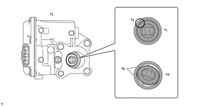
*1
Electric EGR Control Valve Assembly
-
-
*a
Part A
*b
Clearance
*c
OK
*d
NG
OK
No light passes through (there is no clearance between the valve and body).
If light passes through (there is clearance between the valve and body), replace the electric EGR control valve assembly.
Tip:Light passes through part A shown in the illustration even if the valve is completely closed, this is not a malfunction.
Remove the diesel throttle body assembly, intake air connector and EGR pipe connector.
Remove the deposits from the parts and clean them.
Note:When cleaning the electric EGR control valve assembly and the diesel throttle body assembly, use a piece of cloth with cleaning solvent. Spraying solvent directly onto these parts or soaking the parts in solvent may damage the parts.
Extreme care must be taken to prevent the removed deposits from falling into the engine unit during cleaning.
Tip:Remove the intake manifold from the cylinder head when it has to be cleaned.
Do not leave any deposits in the electric EGR control valve assembly when cleaning the valve.
Result
Proceed to
OK
NG
PERFORM ACTIVE TEST USING GTS (DIESEL THROTTLE TARGET ANGLE)
Connect the GTS to the DLC3.
Turn the ignition switch to ON and turn the GTS on.
Enter the following menus: Powertrain / Engine and ECT / Active Test / Diesel Throttle Target Angle / Data List / Actual Throttle Position.
Powertrain > Engine and ECT > Active Test
Active Test Display
Diesel Throttle Target Angle
Data List Display
Actual Throttle Position
When continuously changing the Active Test value to 100, 70, 40, 10, 40, 70 and 100%, check that Actual Throttle Position smoothly changes to the set opening angle.
OK
Value smoothly changes to the set opening angle.
Result
Proceed to
OK
NG
CONFIRM WHETHER MALFUNCTION HAS BEEN SUCCESSFULLY REPAIRED
Check whether the malfunction has been successfully repaired.
OK
Malfunction has been repaired successfully.
Result
Proceed to
OK
NG
BASIC INSPECTION
Check the fuel quality.
Check the fuel line for air.
Check the fuel system for blockages.
Check the air filter.
Check the engine oil.
Check the engine coolant.
Check the engine idling speed and maximum engine speed.
Check the vacuum pump.
OK
Each inspection result is normal.
Result
Proceed to
OK
NG
NG REPAIR OR REPLACE MALFUNCTIONING PARTS
CHECK ENGINE MOUNTING INSULATOR
Visually check that the engine mounting insulator is installed correctly and is not crooked or twisted.
OK
No abnormalities.
Result
Proceed to
OK
NG
NG REPAIR OR REPLACE ENGINE MOUNTING INSULATOR
CHECK INTAKE SYSTEM DEPOSIT
Check if 3 mm (0.12 in.) or more of carbon has accumulated on the intake manifold, cylinder head, etc. and if so, clean it off.
Result
Proceed to
NEXT
CONFIRM WHETHER MALFUNCTION HAS BEEN SUCCESSFULLY REPAIRED
Result
Proceed to
NEXT
NEXT END
PERFORM ACTIVE TEST USING GTS (CONTROL THE SELECT CYLINDER FUEL CUT)
Tip:Use this Active Test to determine the malfunctioning cylinder.
Connect the GTS to the DLC3.
Start the engine and turn the GTS on.
Enter the following menus: Powertrain / Engine and ECT / Active Test / Control the Select Cylinder Fuel Cut.
Powertrain > Engine and ECT > Active Test
Tester Display
Control the Select Cylinder Fuel Cut
Tip:DTCs may be output after this Active Test. Make sure to check for DTCs after this Active Test. If any DTCs are output, make sure to clear them.
If the engine idle speed does not change when a injector assembly is disabled, the cylinder being tested is malfunctioning.
If the cylinder being tested is normal, there will be a significant change in idle speed when the fuel injection is stopped for that cylinder.
Result
Proceed to
NEXT
READ VALUE USING GTS (ENGINE SPEED OF CYL #1 TO #4)
Tip:The speed of each cylinder can be measured (compression test) by using the GTS.
For the compression test, perform Active Test using GTS (Check the Cylinder Compression) and crank the engine for approximately 10 seconds. At this time, the speed of each cylinder is measured. If the speed of one cylinder is higher than the other cylinders, the compression pressure of that cylinder is determined to be lower than the other cylinders.
Warm up the engine.
Turn the ignition switch off.
Connect the GTS to the DLC3.
Turn the ignition switch to ON and turn the GTS on.
Enter the following menus: Powertrain / Engine and ECT / Active Test / Check the Cylinder Compression / Data List / Engine Speed of Cyl #1, Engine Speed of Cyl #2, Engine Speed of Cyl #3, Engine Speed of Cyl #4 and Av Engine Speed of All Cyl.
Powertrain > Engine and ECT > Active Test
Active Test Display
Check the Cylinder Compression
Data List Display
Engine Speed of Cyl #1
Engine Speed of Cyl #2
Engine Speed of Cyl #3
Engine Speed of Cyl #4
Av Engine Speed of All Cyl
Push the snapshot button to turn the snapshot function on.
Tip:Using the snapshot function, data can be recorded during the Active Test.
While the engine is not running, press the Active button to Change the Cylinder Compression to ON.
Tip:After performing the above procedure, Check the Cylinder Compression will start. Fuel injection for all cylinders is prohibited and each cylinder engine speed measurement enters standby mode.
Crank the engine for about 10 seconds.
Monitor the engine speed (Engine Speed of Cyl #1 to #4, Av Engine Speed of All Cyl) displayed on the GTS.
Tip:After approximately 10 seconds of engine cranking, the engine speed measurement of each cylinder will change to the actual engine speed.
Note:Do not crank the engine continuously for 20 seconds or more.
If Check the Cylinder Compression needs to be performed after it is turned ON and performed once, press Exit to return to the Active Test menu screen. Then perform Check the Cylinder Compression again.
Use a fully-charged battery.
Stop cranking the engine, and then change "Check the Cylinder Compression" to OFF after the engine stops.
Note:If the Active Test is changed to OFF while the engine is being cranked, the engine will start.
Push the snapshot button to turn the snapshot function off.
Select "Stored Data" on the GTS screen, select the recorded data and display the data as a graph.
Tip:If the data is not displayed as a graph, the change of the values cannot be observed.
Check the change in engine speed values.
Result
Result
Proceed to
Except below
A
The values of Engine Speed Cyl #1 to #4 are within +/-10 rpm of each other.
B
Tip:When cranking, if the speed of a cylinder is approximately 100 rpm more than the other cylinders, there is probably a complete loss of compression in that cylinder.
B REPLACE INJECTOR ASSEMBLY OF MALFUNCTIONING CYLINDERClick here
CHECK CYLINDER COMPRESSION PRESSURE OF MALFUNCTIONING CYLINDER
Check the cylinder compression pressure.
Result
Proceed to
OK
NG
NG CHECK ENGINE TO DETERMINE CAUSE OF LOW COMPRESSION
REPLACE INJECTOR ASSEMBLY OF MALFUNCTIONING CYLINDER
Replace the injector assembly.
Result
Proceed to
NEXT
PERFORM REGISTRATION AND INITIALIZATION
Register the injector compensation codes.
Perform Pilot Quantity Learning Values Reset.
Result
Proceed to
NEXT
BLEED AIR FROM FUEL SYSTEM
Bleed the air from the fuel system.
Result
Proceed to
NEXT
CONFIRM WHETHER MALFUNCTION HAS BEEN SUCCESSFULLY REPAIRED
Result
Proceed to
NEXT
NEXT END
REPLACE INJECTOR ASSEMBLY OF ALL CYLINDERS
Replace the injector assemblies.
Result
Proceed to
NEXT
PERFORM REGISTRATION AND INITIALIZATION
Register the injector compensation codes.
Perform Pilot Quantity Learning Values Reset.
Result
Proceed to
NEXT
BLEED AIR FROM FUEL SYSTEM
Bleed the air from the fuel system.
Result
Proceed to
NEXT
CONFIRM WHETHER MALFUNCTION HAS BEEN SUCCESSFULLY REPAIRED
Result
Proceed to
NEXT
NEXT END
PERFORM REGISTRATION AND INITIALIZATION
Register the injector compensation codes.
Perform Pilot Quantity Learning Values Reset.
Result
Proceed to
NEXT
CONFIRM WHETHER MALFUNCTION HAS BEEN SUCCESSFULLY REPAIRED
Result
Proceed to
NEXT
NEXT END
CHECK HARNESS AND CONNECTOR (SUCTION CONTROL VALVE - ECM)
Disconnect the suction control valve connector.
Disconnect the ECM connector.
Measure the resistance according to the value(s) in the table below.
Standard Resistance
Tester Connection
Condition
Specified Condition
B123-2 - B212-30 (PCV)
Always
Below 1 Ω
B123-2 or B212-30 (PCV) - Body ground and other terminals
Always
10 kΩ or higher
Result
Proceed to
OK
NG
NG REPAIR OR REPLACE HARNESS OR CONNECTOR
CHECK IF FUEL IS BEING SUPPLIED TO SUPPLY PUMP ASSEMBLY
Disconnect the inlet hose from the supply pump assembly.
Operate the priming pump and check that fuel is being supplied to the supply pump assembly.
OK
Fuel is properly supplied to the supply pump assembly when the priming pump is operated.
Tip:When there is a lack of fuel, fuel pressure drops.
Check that the fuel filter is not clogged.
Result
Proceed to
OK
NG
OK REPLACE SUPPLY PUMP ASSEMBLYClick here
CHECK AND REPLACE CLOGGED FUEL PIPE (INCLUDING FUEL FREEZING) (FUEL TANK - SUPPLY PUMP ASSEMBLY)
Check and replace the clogged fuel pipe.
Result
Proceed to
NEXT
BLEED AIR FROM FUEL SYSTEM
Bleed the air from the fuel system.
Result
Proceed to
NEXT
CONFIRM WHETHER MALFUNCTION HAS BEEN SUCCESSFULLY REPAIRED
Result
Proceed to
NEXT
NEXT END
CHECK AND REPLACE FUEL INLET LINE
Check the following items, and repair or replace the malfunctioning part if necessary.
Check that the fuel filter is not clogged.
Check for fuel freezing in the fuel line.
Check for clogs or leaks in the fuel pipe and hose between the fuel tank and supply pump assembly.
Result
Proceed to
NEXT
BLEED AIR FROM FUEL SYSTEM
Bleed the air from the fuel system.
Result
Proceed to
NEXT
READ VALUE USING GTS (COMMON RAIL PRESSURE AND TARGET COMMON RAIL PRESSURE)
Connect the GTS to the DLC3.
Start the engine.
Turn the GTS on.
Enter the following menus: Powertrain / Engine and ECT / Data List / Common Rail Pressure and Target Common Rail Pressure.
Powertrain > Engine and ECT > Data List
Tester Display
Target Common Rail Pressure
Common Rail Pressure
Check that the fuel pressure of the common rail is within the specification below.
Standard
Common Rail Pressure is within +/-10000 kPa of Target Common Rail Pressure when engine is idling and running at 3000 rpm without load.
Result
Proceed to
OK
NG
OK END
REPLACE SUPPLY PUMP ASSEMBLY
Replace the supply pump assembly.
Result
Proceed to
NEXT
BLEED AIR FROM FUEL SYSTEM
Bleed the air from the fuel system.
Result
Proceed to
NEXT
READ VALUE USING GTS (COMMON RAIL PRESSURE AND TARGET COMMON RAIL PRESSURE)
Connect the GTS to the DLC3.
Start the engine.
Turn the GTS on.
Enter the following menus: Powertrain / Engine and ECT / Data List / Common Rail Pressure and Target Common Rail Pressure.
Powertrain > Engine and ECT > Data List
Tester Display
Target Common Rail Pressure
Common Rail Pressure
Check that the fuel pressure of the common rail is within the specification below.
Standard
Common Rail Pressure is within +/-10000 kPa of Target Common Rail Pressure when engine is idling and running at 3000 rpm without load.
Result
Proceed to
OK
NG
NG REPLACE COMMON RAIL ASSEMBLYClick here
CONFIRM WHETHER MALFUNCTION HAS BEEN SUCCESSFULLY REPAIRED
Result
Proceed to
NEXT
NEXT END
REPLACE COMMON RAIL ASSEMBLY
Replace the common rail assembly.
Result
Proceed to
NEXT
BLEED AIR FROM FUEL SYSTEM
Bleed the air from the fuel system.
Result
Proceed to
NEXT
READ VALUE USING GTS (COMMON RAIL PRESSURE AND TARGET COMMON RAIL PRESSURE)
Connect the GTS to the DLC3.
Start the engine.
Turn the GTS on.
Enter the following menus: Powertrain / Engine and ECT / Data List / Common Rail Pressure and Target Common Rail Pressure.
Powertrain > Engine and ECT > Data List
Tester Display
Target Common Rail Pressure
Common Rail Pressure
Check that the fuel pressure of the common rail is within the specification below.
Standard
Common Rail Pressure is within +/-10000 kPa of Target Common Rail Pressure when engine is idling and running at 3000 rpm without load.
Result
Proceed to
NEXT
NEXT END