COMPRESSOR INSTALLATION
PROCEDURE
-
ADJUST COMPRESSOR OIL
-
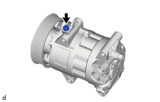
When replacing the compressor with pulley assembly with a new one, gradually discharge the refrigerant gas from the service valve. Then drain the following amount of oil from the new compressor with pulley assembly before installation, so that the amount of oil contained in it is the same as that in the cooler compressor with pulley assembly to be replaced.
Standard Standard: (The amount of oil inside a new cooler compressor with pulley assembly: 80 (+15) cc (2.82 (+0.51) fl.oz.)) - (The amount of oil remaining in the removed compressor with pulley assembly A + oil remaining in the reserve chamber B) = (The amount of oil to be removed when replacing the cooler compressor with pulley assembly) Tech Tips
A new cooler compressor with pulley assembly is filled with sufficient oil for the whole cycle. Therefore, it is necessary to drain residual oil from the condenser and cooling unit. Example: If A is 20 cc (0.68 fl.oz.) and B is 25 cc (0.85 fl.oz.), A+B=45 cc (1.52 fl.oz.). Since this time 80 cc (2.82fl.oz.) - 45 cc (1.52 fl.oz.) =15 cc (0.51 fl.oz.), drain 15 cc (0.51 fl.oz.) of the oil from the new cooler compressor with pulley assembly.
Note
-
When A + B exceeds the standard oil fill volume specified for the compressor with pulley assembly by part number, install the compressor with pulley assembly without adjusting the oil volume. Example: If A is 40 cc (1.35 fl.oz.) and B is 25 cc (0.85 fl.oz.), A+B is greater than 80 cc (2.82 fl.oz.) and less than 95 cc (2.64 fl.oz.), so install the cooler compressor with pulley assembly as is.
-
When checking the compressor oil level, observe the precautions for cooler removal/installation.
-
If a new cooler compressor with pulley assembly is installed without removing the same amount of oil as is remaining in the vehicle pipes, the amount of oil will be too large. This prevents heat exchange in the refrigerant cycle and will cause a refrigeration failure.
-
If the amount of oil remaining in the removed compressor with pulley assembly is too low, check for an oil leak.
-
Use VC100YF or equivalent for compressor oil.(for VALEO Made)
-
Use ND-OIL 8 or equivalent for compressor oil.(for DENSO Made)
-
-
-
INSTALL COMPRESSOR WITH PULLEY ASSEMBLY
-
Using an E8 "TORX" socket wrench, temporarily install the compressor with pulley assembly with the 2 stud bolts.
- Torque:
- 9.8 N*m { 100 kgf*cm, 87 in.*lbf }
-
Temporarily install the 2 bolts and 2 nuts.
-
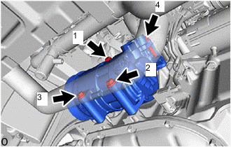
Tighten the 2 bolts and 2 nuts to install the compressor with pulley assembly in the order as shown in the illustration.
- Torque:
- 25 N*m { 255 kgf*cm, 18 ft.*lbf }
-
Connect the connector.
-
-
CONNECT SUCTION HOSE SUB-ASSEMBLY
-
Remove the vinyl tape from the suction hose sub-assembly.
-
Sufficiently apply compressor oil to a new O-ring and the fitting surface of the compressor with pulley assembly.
Compressor Oil for VALEO Made VC100YF or equivalent for DENSO Made ND-OIL 8 or equivalent -
Install the O-ring to the suction hose sub-assembly.
-
Connect the suction hose sub-assembly to the compressor with pulley assembly with the bolt.
- Torque:
- 9.8 N*m { 100 kgf*cm, 87 in.*lbf }
-
-
CONNECT DISCHARGE HOSE SUB-ASSEMBLY
-
Remove the vinyl tape from the discharge hose sub-assembly.
-
Apply sufficient compressor oil to a new O-rings and fitting surfaces of the cooler compressor with pulley assembly.
Compressor Oil for VALEO Made VC100YF or equivalent for DENSO Made ND-OIL 8 or equivalent -
Install the O-ring to the discharge hose sub-assembly.
Note
Keep the O-ring and O-ring fitting surface free of foreign matter.
-
Connect the suction hose sub-assembly to the compressor with pulley assembly with the bolt.
- Torque:
- 9.8 N*m { 100 kgf*cm, 87 in.*lbf }
-
-
INSTALL FAN AND GENERATOR V BELT
-
INSTALL NO. 1 ENGINE UNDER COVER
-
CHARGE AIR CONDITIONING SYSTEM WITH REFRIGERANT (for HFC-134a(R134a))
-
CHARGE AIR CONDITIONING SYSTEM WITH REFRIGERANT (for HFO-1234yf(R1234yf))
-
WARM UP WARM UP ENGINE (for HFC-134a(R134a))
-
WARM UP WARM UP ENGINE (for HFO-1234yf(R1234yf))
-
INSPECT FOR REFRIGERANT LEAK (for HFC-134a(R134a))
-
INSPECT FOR REFRIGERANT LEAK (for HFO-1234yf(R1234yf))