БЛОК ДВИГАТЕЛЯ ПОВТОРНАЯ СБОРКА

Tech Tips
Perform "Inspection After Repairs" after replacing the piston sub-assembly or piston ring Click here.
-
INSTALL TIGHT PLUG
Tech Tips
If coolant leaks from a tight plug or a plug is corroded, replace it.

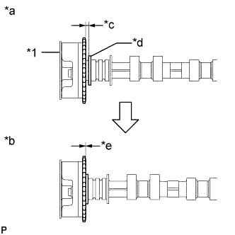
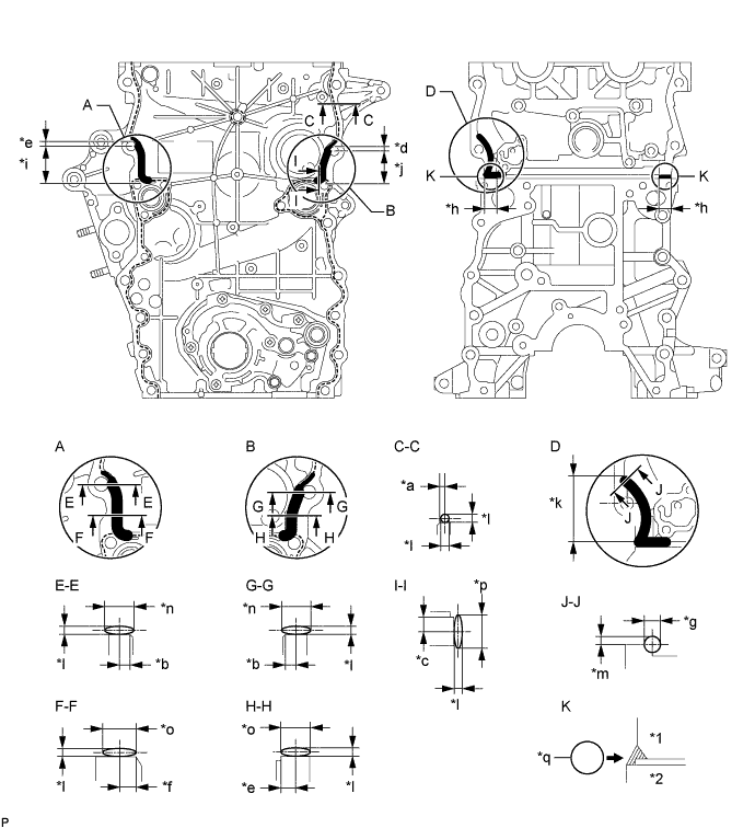
Text in Illustration *a Front Side *b Intake Side *c Rear Side *d Exhaust Side *e 1.0 mm (0.0394 in.) - -
-
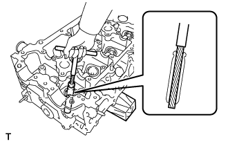
Apply adhesive to new tight plugs.
Adhesive Toyota Genuine Adhesive 1324, Three Bond 1324 or equivalent -
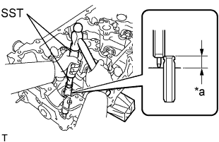
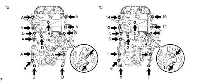
Using SST, tap in the tight plug labeled A.
- SST
- 09950-60010 ( 09951-00300 )
- 09950-70010 ( 09951-07100 )
-
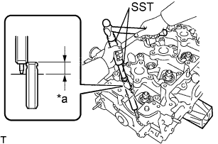
Using SST, tap in the 8 tight plugs labeled B and D.
- SST
- 09950-60010 ( 09951-00350 )
- 09950-70010 ( 09951-07100 )
-
Using SST, tap in the tight plugs labeled C.
- SST
- 09950-60010 ( 09951-00400 )
- 09950-70010 ( 09951-07100 )
-
-
INSTALL STUD BOLT
Tech Tips
If a stud bolt is deformed or its threads are damaged, replace it.
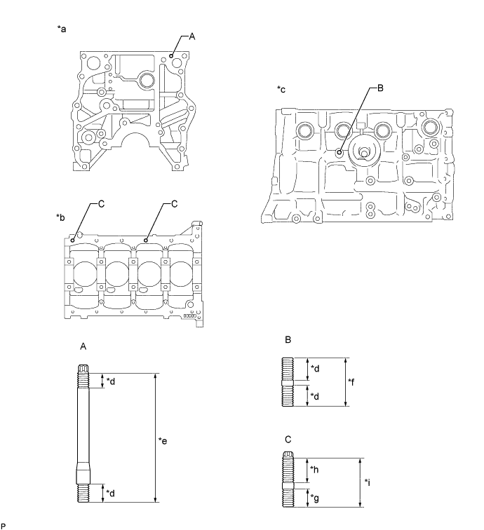
Text in Illustration *a Front Side *b Lower Side *c Exhaust Side *d 12 mm (0.472 in.) *e 85 mm (3.35 in.) *f 37 mm (1.46 in.) *g 13 mm (0.512 in.) *h 20 mm (0.787 in.) *i 35 mm (1.38 in.) - -
-
Using an E8 "TORX" socket wrench, install the stud bolts labeled A.
- Torque:
- 7.5 N*m { 76 kgf*cm, 66 in.*lbf }
-
Apply adhesive to the hole for the stud bolt labeled B in the cylinder block. Install the stud bolt labeled B.
- Torque:
- 7.5 N*m { 76 kgf*cm, 66 in.*lbf }
Tech Tips
When reusing a stud bolt, apply adhesive to the bolt before installing it.
Adhesive Toyota Genuine Adhesive 1344, Three Bond 1344 or equivalent -
Using an E7 "TORX" socket wrench, install the stud bolts labeled C.
- Torque:
- 7.5 N*m { 76 kgf*cm, 66 in.*lbf }
-
-
INSTALL STRAIGHT PIN
Tech Tips
It is not necessary to remove a straight pin unless it is being replaced.
-
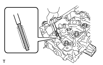
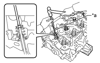
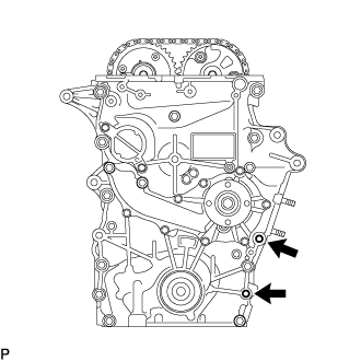
Using a plastic-faced hammer, tap in new straight pins to the cylinder block.
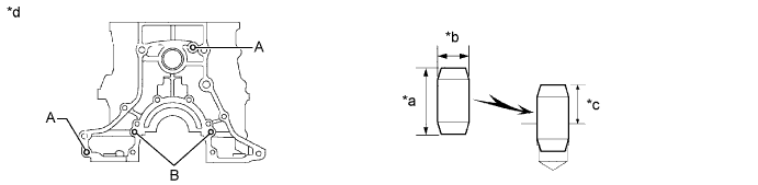
Text in Illustration *a Height *b Wide *c Protrusion Height *d Rear Side Standard Straight Pin Item Height Width Protrusion Pin A 22 mm (0.866 in.) 10 mm (0.394 in.) 13 mm (0.512 in.) Pin B 14 mm (0.551 in.) 6.0 mm (0.236 in.) 5.5 mm (0.217 in.)
-
-
INSTALL RING PIN
Tech Tips
It is not necessary to remove a ring pin unless it is being replaced.
-
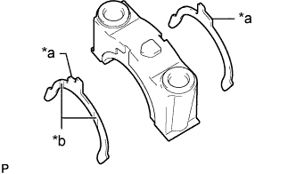
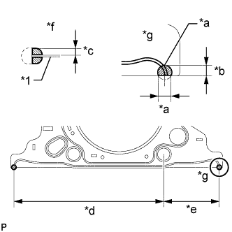
Using a plastic-faced hammer, tap in new ring pins to the cylinder block.
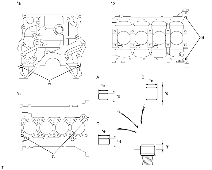
Text in Illustration *a Front Side *b Lower Side *c Upper Side *d Height *e Width *f Protrusion Standard Ring Pin Item Height Width Protrusion Pin A 9.0 mm (0.354 in.) 11 mm (0.433 in.) 3.5 to 4.5 mm (0.138 to 0.177 in.) Pin B 20 mm (0.787 in.) 14 mm (0.511 in.) 7.0 to 9.0 mm (0.276 to 0.354 in.) Pin C 14 mm (0.511 in.) 15 mm (0.591 in.) 7.5 to 9.5 mm (0.295 to 0.374 in.)
-
-
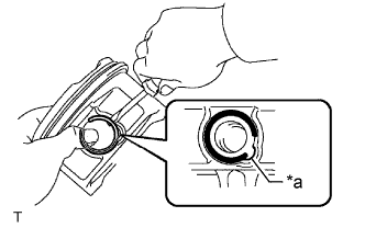
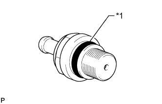
INSTALL CYLINDER BLOCK WATER DRAIN COCK SUB-ASSEMBLY
-
Apply adhesive to the cylinder block water drain cock sub-assembly.
Adhesive Toyota Genuine Adhesive 1324, Three Bond 1324 or equivalent -
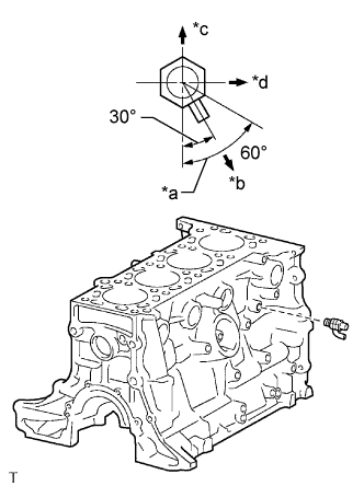
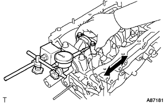
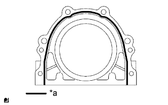
Text in Illustration *a Allowable Range *b Target Direction *c Upper Side *d Front Install the cylinder block water drain cock sub-assembly as shown in the illustration.
- Torque:
- 25 N*m { 250 kgf*cm, 18 ft.*lbf }
Note
-
Do not rotate the cylinder block water drain cock sub-assembly more than 1 revolution (360°) after tightening the cylinder block water drain cock sub-assembly to the specified torque.
-
Do not loosen the cylinder block water drain cock sub-assembly to adjust it. If an adjustment is necessary, remove the cylinder block water drain cock sub-assembly and reinstall it.
-
Install the water drain cock plug to the cylinder block water drain cock sub-assembly.
- Torque:
- 13 N*m { 130 kgf*cm, 9 ft.*lbf }
-
-
INSTALL NO. 1 OIL NOZZLE SUB-ASSEMBLY
-
Using an E7 "TORX" socket wrench, install the 4 No. 1 oil nozzle sub-assemblies.
- Torque:
- 7.0 N*m { 71 kgf*cm, 62 in.*lbf }
-
-
INSTALL CONNECTING ROD SMALL END BUSH
-
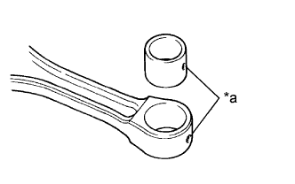
Text in Illustration *a Oil Hole Align the oil holes of a new connecting rod small end bush and the connecting rod.
-
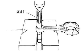
Using SST and a press, press in the connecting rod small end bush.
- SST
- 09222-30010
-
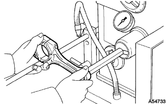
Using a pin hole grinder, hone the connecting rod small end bush to obtain the standard specified clearance Click here between the connecting rod small end bush and piston pin.
-
Check that the piston pin fits at normal room temperature.
-
Coat the piston pin with engine oil, and push it into the connecting rod with your thumb.
-
-
-
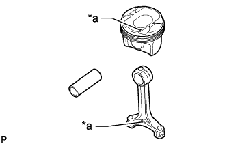
INSTALL PISTON WITH PIN SUB-ASSEMBLY
Tech Tips
Perform "Inspection After Repairs" after replacing the piston sub-assembly Click here.
-
Assemble the piston and connecting rod.
-

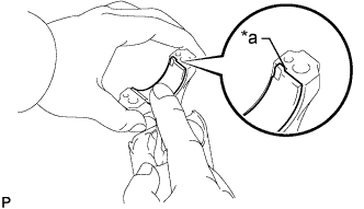
Text in Illustration *a Service Hole Cutout Portion Using a screwdriver, install a new snap ring at one end of the piston pin hole.
Tech Tips
Make sure that the end gap of the snap ring is not aligned with the service hole cutout portion of the piston.
-
Gradually heat the piston to approximately 80 to 90°C (176 to 194°F).
-
Coat the piston pin with engine oil.
-
Text in Illustration *a Front Mark Align the front marks of the piston and connecting rod and push in the piston pin with your thumb.
Tech Tips
The piston and pin are a matched set.
-
Text in Illustration *a Service Hole Cutout Portion Using a screwdriver, install a new snap ring at the other end of the piston pin hole.
Tech Tips
Make sure that the end gap of the snap ring is not aligned with the service hole cutout portion of the piston.
-
Check the fitting condition between the piston and piston pin by trying to move the piston back and forth on the piston pin.
-
-
-
INSTALL PISTON RING SET
Tech Tips
Perform "Inspection After Repairs" after replacing the piston ring Click here.
-
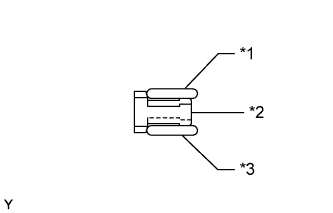
Text in Illustration *1 Upper Oil Ring Side Rail *2 Oil Ring Expander *3 Lower Oil Ring Side Rail Install the oil ring expander and 2 oil ring side rails by hand.
-
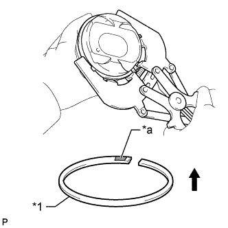
Text in Illustration *1 No. 2 Compression Ring *a Code Mark (2N) 
Upward Using a piston ring expander, install the 2 compression rings with the code mark as shown in the illustration.
Note
-
The No. 1 compression ring is reversible.
-
Install the No. 2 compression ring with the code mark (2N) facing upward.
-
-
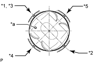
Text in Illustration *1 No. 1 Compression Ring *2 No. 2 Compression Ring *3 Oil Ring Expander *4 Upper Oil Ring Side Rail *5 Lower Oil Ring Side Rail *a Front Mark Position the piston rings so that the ring ends are as shown in the illustration.
Note
Do not align the compression ring ends.
-
-
INSTALL CRANKSHAFT BEARING
Note
Do not apply engine oil to the contact area or backside of the crankshaft bearing.
Tech Tips
The crankshaft bearing cap bolts are tightened in 2 progressive steps.
-
Clean the main journal, and both surfaces of the crankshaft bearing.
-
Install the upper crankshaft bearing.
-
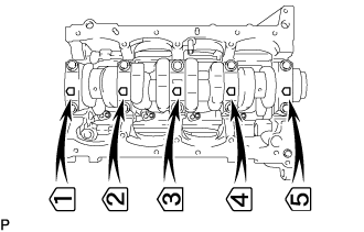
Text in Illustration *a CORRECT *b INCORRECT *c Oil Groove Install the upper crankshaft bearing to the cylinder block as shown in the illustration.
Reference (Difference in Dimension of Cylinder Block and Crankshaft Bearing) Item Specified Condition # 1, 5 journal 3.83 mm (0.151 in.) # 3 journal 1.74 mm (0.0685 in.) # 2, 4 journal 2.75 mm (0.1083 in.) Note
-
Do not apply engine oil to the upper crankshaft bearings or their contact surfaces.
-
Both sides of the oil groove in the cylinder block should be visible through the oil feed holes in the bearing. The amount visible on each side of the holes should be equal.
-
-
-
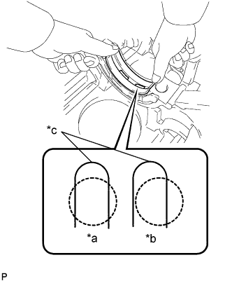
Install the lower crankshaft bearing.
-
Install the lower crankshaft bearing to the crankshaft bearing cap.
-
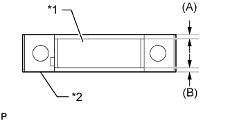
Text in Illustration *1 Lower Crankshaft Bearing *2 Crankshaft Bearing Cap Using a vernier caliper, measure the distance between the crankshaft bearing cap edge and lower crankshaft bearing edge.
Dimension (A - B) or (B - A) 0.3 mm (0.0118 in.) or less Reference (Dimension of (A) or (B)) Item Specified Condition # 1, 5 journal 3.83 mm (0.151 in.) # 3 journal 1.74 mm (0.0685 in.) # 2, 4 journal 2.75 mm (0.108 in.) Note
Do not apply engine oil to the crankshaft bearings or their contact surfaces.
-
-
With the upper crankshaft bearing and lower crankshaft bearing installed, use a plastic-faced hammer to install the crankshaft bearing caps to the cylinder block.
Note
Make sure that the crankshaft bearing caps are installed in the correct positions and facing in the correct direction.
-
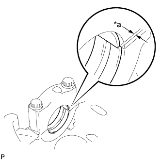
Text in Illustration *a Misalignment Using a vernier caliper, measure the amount of misalignment between the upper crankshaft bearing and lower crankshaft bearing as shown in the illustration.
Standard misalignment 0.9 mm (0.0354 in.) or less -
Remove the crankshaft bearing cap.
-
Apply engine oil to the upper crankshaft thrust washers.
-
Text in Illustration *a Oil Groove Install the 2 upper crankshaft thrust washers to the No. 3 journal position of the cylinder block with the oil grooves facing outward.
Note
Be careful when installing the upper and lower crankshaft thrust washers as they are similar but cannot be interchanged.
-
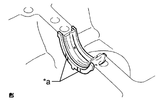
Text in Illustration *a Claw *b Oil Groove Install the 2 lower crankshaft thrust washers to the No. 3 crankshaft bearing cap with the grooves facing outward.
Note
Be careful when installing the upper and lower crankshaft thrust washers as they are similar but cannot be interchanged. The lower crankshaft thrust washers have a claw as shown in the illustration.
-
-
Apply engine oil to the lower crankshaft bearing.
-
-
INSTALL CRANKSHAFT
-
Apply engine oil to the upper crankshaft bearing, and then place the crankshaft on the cylinder block.
-
Install the 5 crankshaft bearing caps to their proper locations.
-
Install the crankshaft bearing cap bolts.
-
Apply a light coat of engine oil to the threads and under the heads of the bearing cap bolts.
-
Temporarily install the crankshaft bearing cap bolts.
Tech Tips
The main bearing cap bolts are tightened in 2 progressive steps.
-
Step 1:
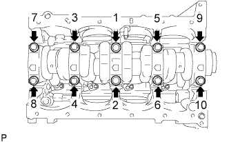
Uniformly tighten the 10 crankshaft bearing cap bolts in the sequence shown in the illustration.
- Torque:
- 39 N*m { 398 kgf*cm, 29 ft.*lbf }
If any of the crankshaft bearing cap bolts does not meet the torque specification, replace the crankshaft bearing cap bolt.
-
Mark the front of the bearing cap bolts with paint.
-
Step 2:
Tighten the bearing cap bolts 90° in the sequence shown in step 1.
-
Check that the paint marks are now at a 90° angle to the front.
-
-
Check that the crankshaft turns smoothly.
-
-
INSPECT CRANKSHAFT THRUST CLEARANCE
-
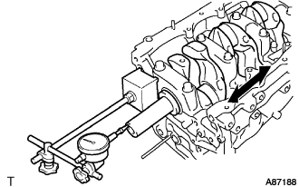
С помощью индикатора часового типа измерьте осевой зазор, двигая коленчатый вал вперед и назад с помощью отвертки.
Номинальный осевой зазор 0,02 - 0,22 мм (0,000787 - 0,00866 дюйма) Максимально допустимый осевой зазор 0,30 мм (0,0118 дюйма) Если осевой зазор превышает максимально допустимое значение, замените комплект упорных шайб. При необходимости замените коленчатый вал.
Толщина упорной шайбы 2,440 - 2,490 мм (0,0961 - 0,0980 дюйма)
-
-
INSTALL CONNECTING ROD BEARING
-
Text in Illustration *a Claw Align the connecting rod bearing claw with the groove of the connecting rod or connecting rod cap.
-
Install the bearings in the connecting rod and connecting rod cap.
Note
Clean the backside of the bearing and the bearing surface of the connecting rod.
-
-
INSTALL PISTON SUB-ASSEMBLY WITH CONNECTING ROD
-
Apply engine oil to the cylinder walls, the pistons, and the surfaces of the connecting rod bearings.
-
Text in Illustration *1 No. 1 Compression Ring *2 No. 2 Compression Ring *3 Oil Ring Expander *4 Upper Oil Ring Side Rail *5 Lower Oil Ring Side Rail *a Front Mark Position the piston rings so that the ring ends are as shown in the illustration.
Note
Do not align the compression ring ends.
-
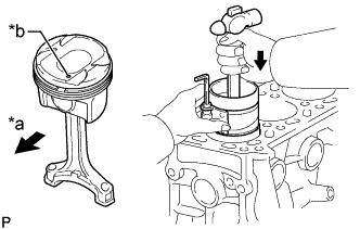
Text in Illustration *a Front *b Front Mark Using a piston ring compressor, push the numbered piston and connecting rod assembly into the correct cylinder with the front mark of the piston facing forward.
-
Match the numbered connecting rod cap with the correct connecting rod.
-
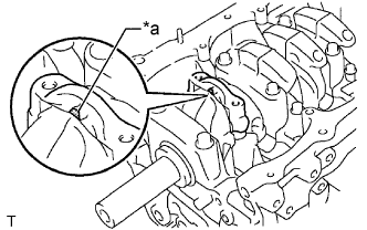
Text in Illustration *a Front Mark Check that the front mark of the connecting rod cap is facing forward.
-
Install the connecting rod cap bolts.
Tech Tips
The connecting rod cap bolts are tightened in 2 progressive steps.
-
Apply a light coat of engine oil to the threads and under the heads of the connecting rod cap bolts.
-
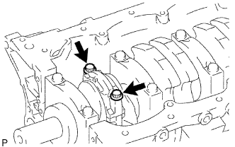
Step 1:
Install and alternately tighten the bolts of the connecting rod cap in several steps.
- Torque:
- 25 N*m { 250 kgf*cm, 18 ft.*lbf }
-
Mark the front of each connecting rod cap bolt with paint.
-
Step 2:
Tighten the cap bolts 90° as shown.
-
Check that the paint marks are now at a 90° angle to the front.
-
-
Check that the crankshaft turns smoothly.
-
-
INSPECT CONNECTING ROD THRUST CLEARANCE
-
С помощью индикатора часового типа измерьте осевой зазор при движении шатуна назад и вперед.
Номинальный осевой зазор 0,15 - 0,35 мм (0,00591 - 0,0138 дюйма) Максимально допустимый осевой зазор 0,40 мм (0,0157 дюйма) Если осевой зазор превышает максимально допустимую величину, замените шатун в сборе. При необходимости замените коленчатый вал.
-
-
INSTALL INTAKE VALVE GUIDE BUSH
-
Using a caliper gauge, measure the bush bore diameter of the cylinder head.
Standard Bush Bore Diameter Item Specified Condition STD 10.285 to 10.306 mm (0.405 to 0.406 in.) O/S 0.05 10.335 to 10.356 mm (0.407 to 0.408 in.) If the bush bore diameter of the cylinder head is more than 10.306 mm (0.406 in.), machine the bush bore so that the diameter is between 10.335 and 10.356 mm (0.407 and 0.408 in.).
If the bush bore diameter of the cylinder head is more than 10.356 mm (0.408 in.), replace the cylinder head sub-assembly.
-
Select a new intake valve guide bush.
New Valve Guide Bush Item Specified Condition Bush Diameter 10.333 to 10.344 mm (0.4068 to 0.4072 in.) 10.383 to 10.394 mm (0.4088 to 0.4092 in.) Bush to be Used STD O/S 0.05 Tech Tips
Standard intake valve guide bush length: 43.0 to 44.0 mm (1.69 to 1.73 in.)
-
Heat the cylinder head sub-assembly to 80 to 100°C (176 to 212°F).
-
Place the cylinder head sub-assembly on wooden blocks.
-
Text in Illustration *a Protrusion Height Using SST and a hammer, tap in a new intake valve guide bush to the specified protrusion height.
- SST
- 09201-01055
- 09950-70010 ( 09951-07100 )
Standard protrusion height 9.8 to 10.2 mm (0.386 to 0.402 in.) -
Using a sharp 5.5 mm reamer, ream the intake valve guide bush to obtain the standard clearance between the intake valve guide bush and valve stem.
Standard oil clearance 0.025 to 0.060 mm (0.000984 to 0.00236 in.)
-
-
INSTALL EXHAUST VALVE GUIDE BUSH
-
Using a caliper gauge, measure the bush bore diameter of the cylinder head.
Standard Bush Bore Diameter Item Specified Condition STD 10.285 to 10.306 mm (0.405 to 0.406 in.) O/S 0.05 10.335 to 10.356 mm (0.407 to 0.408 in.) If the bush bore diameter of the cylinder head is more than 10.306 mm (0.406 in.), machine the bush bore so that the diameter is between 10.335 and 10.356 mm (0.407 and 0.408 in.).
If the bush bore diameter of the cylinder head is more than 10.356 mm (0.408 in.), replace the cylinder head sub-assembly.
-
Select a new exhaust valve guide bush.
New Valve Guide Bush Item Specified Condition Bush Diameter 10.333 to 10.344 mm (0.4068 to 0.4072 in.) 10.383 to 10.394 mm (0.4088 to 0.4092 in.) Bush to be Used STD O/S 0.05 Tech Tips
Standard exhaust valve guide bush length: 43.0 to 44.0 mm (1.69 to 1.73 in.)
-
Heat the cylinder head sub-assembly to 80 to 100°C (176 to 212°F).
-
Place the cylinder head sub-assembly on wooden blocks.
-
Text in Illustration *a Protrusion Height Using SST and a hammer, tap in a new valve guide bush to the specified protrusion height.
- SST
- 09201-01055
- 09950-70010 ( 09951-07100 )
Standard protrusion height 7.6 to 8.0 mm (0.299 to 0.315 in.) -
Using a sharp 5.5 mm reamer, ream the exhaust valve guide bush to obtain the standard clearance between the exhaust valve guide bush and valve stem.
Standard oil clearance 0.030 to 0.065 mm (0.00118 to 0.00256 in.)
-
-
INSTALL CAMSHAFT BEARING CAP SETTING RING PIN
Note
It is not necessary to remove a ring pin unless it is being replaced.
-
Remove the ring pins.
-
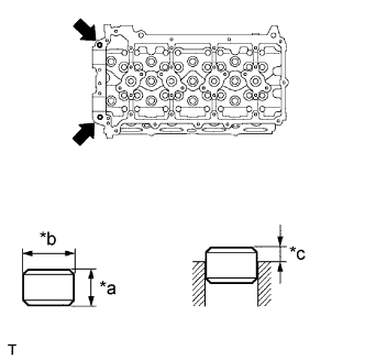
Using a plastic-faced hammer, tap in a new ring pin until the pin stops.
Standard Ring Pin Item Height Width Protrusion Height Ring pin 7 mm (0.276 in.) 10 mm (0.394 in.) 2.5 to 3.8 mm (0.0984 to 0.150 in.) Text in Illustration *a Height *b Width *c Protrusion Height
-
-
INSTALL STUD BOLT
Note
If a stud bolt is deformed or its threads are damaged, replace it.
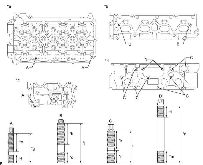
Text in Illustration *a Cylinder Head Upper Side *b Intake Side *c Front Side *d Exhaust Side *e 21 mm (0.827 in.) *f 9 mm (0.354 in.) *g 34 mm (1.34 in.) *h 18 mm (0.709 in.) *i 13 mm (0.512 in.) *j 44 mm (1.73 in.) *k 20 mm (0.787 in.) *l 35 mm (1.38 in.) *m 14 mm (0.551 in.) *n 63 mm (2.48 in.) *o 12 mm (0.472 in.) - -
-
Using E6, E7 and E8 "TORX" socket wrenches, install the stud bolts.
- Torque:
- for stud bolt A
- 3.0 N*m { 31 kgf*cm, 27 in.*lbf }
- for stud bolt B and C
- 7.5 N*m { 76 kgf*cm, 66 in.*lbf }
-
-
INSTALL NO. 1 HEAD STRAIGHT SCREW PLUG
Note
If coolant leaks from a No. 1 head straight screw plug or a plug is corroded, replace it.
-
Using a 10 mm hexagon wrench, install 3 new gaskets and the No. 1 head straight screw plugs.
- Torque:
- 44 N*m { 449 kgf*cm, 32 ft.*lbf }
-
-
INSTALL NO. 2 HEAD STRAIGHT SCREW PLUG
Note
If coolant leaks from the No. 2 head straight screw plug or the plug is corroded, replace it.
-
Using a 19 mm hexagon wrench, install a new gasket and the No. 2 head straight screw plug.
- Torque:
- 140 N*m { 1428 kgf*cm, 103 ft.*lbf }
-
-
INSTALL OIL CONTROL VALVE FILTER
-
Check that no foreign matter is on the mesh part of the filter.
If foreign objects are present, clean the part thoroughly.
-
Using an 8 mm hexagon wrench, install a new gasket and the oil control valve filter with the screw plug.
- Torque:
- 30 N*m { 306 kgf*cm, 22 ft.*lbf }
-
-
INSTALL VALVE SPRING SEAT
-
Install the 16 valve spring seats to the cylinder head sub-assembly.
-
-
INSTALL VALVE STEM OIL SEAL
-
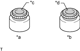
Text in Illustration *a Intake Side *b Exhaust Side *c Gray *d Black Apply a light coat of engine oil to new valve stem oil seals.
Note
Pay attention when installing the intake and exhaust valve stem oil seals. Installing an intake valve stem oil seal to the exhaust side or installing an exhaust valve stem oil seal to the intake side can cause installation problems later.
Tech Tips
The intake valve stem oil seals are gray and the exhaust valve stem oil seals are black.
-
Text in Illustration *1 Valve Stem Oil Seal Using SST, push in the 16 valve stem oil seals to install them.
- SST
- 09201-41020
Note
Failure to use SST will cause the valve stem oil seal to be damaged or improperly seated.
-
-
INSTALL INTAKE VALVE
-
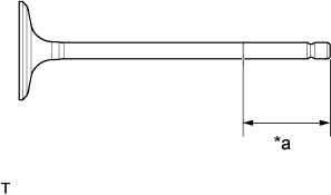
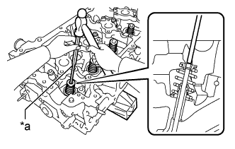
Text in Illustration *a 30 mm (1.18 in.) or more Apply plenty of engine oil to the tip area of the intake valve shown in the illustration.
-
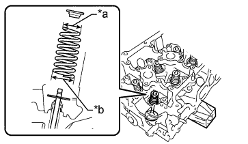
Text in Illustration *a Narrow *b Wide Install the intake valve, inner compression spring and valve spring retainer to the cylinder head.
Note
Install the same parts in the same combination to the original locations.
-
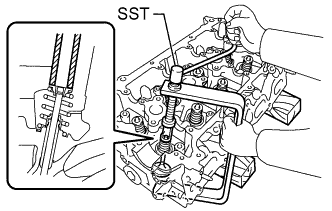
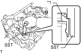
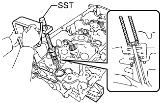
Using SST and wooden blocks, compress the inner compression spring and install the 2 valve spring retainer locks.
- SST
- 09202-70020
- 09202-00021
-
Text in Illustration *a 5 mm Pin Punch Using a 5 mm pin punch and plastic-faced hammer, lightly tap the valve stem tip to ensure a proper fit.
Note
Do not damage the valve stem tip.
-
-
INSTALL EXHAUST VALVE
-
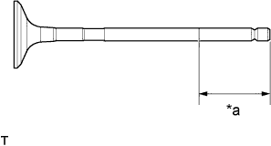
Text in Illustration *a 30 mm (1.18 in.) or more Apply plenty of engine oil to the tip area of the exhaust valve shown in the illustration.
-
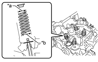
Text in Illustration *a Narrow *b Wide Install the exhaust valve, inner compression spring and valve spring retainer to the cylinder head sub-assembly.
Note
Install the same parts in the same combination to the original locations.
-
Using SST and wooden blocks, compress the inner compression spring and install the 2 valve spring retainer locks.
- SST
- 09202-70020
- 09202-00021
-
Text in Illustration *a 5 mm Pin Punch Using a 5 mm pin punch and plastic-faced hammer, lightly tap the valve stem tip to ensure a proper fit.
Note
Do not damage the valve stem tip.
-
-
INSTALL OIL FILTER BRACKET SUB-ASSEMBLY
-
Install 2 new gaskets and 2 straight screw plugs to the oil filter bracket sub-assembly.
- Torque:
- 27 N*m { 275 kgf*cm, 20 ft.*lbf }
-
Install 2 new O-rings, gasket and oil filter bracket with the union bolt and nut.
- Torque:
- for union bolt
- 69 N*m { 699 kgf*cm, 51 ft.*lbf }
- for nut
- 25 N*m { 255 kgf*cm, 18 ft.*lbf }
Note
Apply a light coat of engine oil to the new O-rings.
-
-
INSTALL OIL FILTER ELEMENT
-
Clean the inside of the oil filter cap, its threads and its O-ring groove.
-
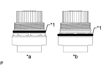
Text in Illustration *1 O-Ring *a CORRECT *b INCORRECT Apply a small amount of engine oil to a new O-ring and install it to the oil filter cap.
Note
-
Be sure to install the O-ring in the proper location, otherwise oil may leak.
-
Do not twist the O-ring.
-
-
Set a new oil filter element in the oil filter cap.
-
Remove any dirt or foreign matter from the installation surface of the engine.
-
Apply a small amount of engine oil to the O-ring again and temporarily install the oil filter cap.
-
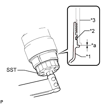
Text in Illustration *1 Oil Filter Cap *2 O-Ring *3 Oil Filter Bracket *a No Gap Using SST, tighten the oil filter cap.
- SST
- 09228-06501
- Torque:
- 25 N*m { 255 kgf*cm, 18 ft.*lbf }
-
-
INSTALL REAR CRANKSHAFT OIL SEAL
-
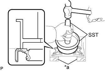
Text in Illustration *a Wooden Block Place the rear engine oil seal retainer on wooden blocks.
-
Using SST, tap in a new rear crankshaft oil seal until its surface is flush with the rear engine oil seal retainer edge.
- SST
- 09223-15030
- 09950-70010 ( 09951-07150 )
Note
Do not tap the rear crankshaft oil seal at an angle.
-
Apply a light coat of MP grease to the lip of a new rear crankshaft oil seal.
Note
-
Do not allow foreign matter to contact the lip of the rear crankshaft oil seal.
-
Do not allow MP grease to contact the dust seal.
-
-
-
INSTALL REAR ENGINE OIL SEAL RETAINER
-
Text in Illustration *a Seal Packing Apply seal packing in a continuous bead as shown in the illustration.
Seal packing Toyota Genuine Seal Packing Black, Three Bond 1207B or equivalent Standard seal width 2.5 to 3.5 mm (0.0984 to 0.138 in.) Note
-
Remove any oil from the contact surface.
-
Install the crankcase within 3 minutes after applying seal packing.
-
Do not start the engine for at least 4 hours after installing.
-
-
Install the rear engine oil seal retainer with the 6 bolts.
- Torque:
- 13 N*m { 133 kgf*cm, 10 ft.*lbf }
Note
Wipe off any seal packing that has leaked out within 10 minutes.
-
-
INSTALL CYLINDER HEAD GASKET
-
Удалите остатки старого герметика (FIPG). Следите за тем, чтобы масло не попало на контактные поверхности головки блока цилиндров и блока цилиндров.
-
Обозначения на рисунке *1 Прокладка головки блока цилиндров *a 7,0 - 9,0 мм (0,276 - 0,354 дюйма) *b 5,0 - 7,0 мм (0,197 - 0,276 дюйма) *c 3,0 - 5,0 мм (0,118 - 0,197 дюйма) *d 166,25 мм (6,55 дюйма) *e 62,25 мм (2,46 дюйма) *f Вид сбоку *g Вид A Нанесите герметик на новую прокладку головки блока цилиндров, как показано на рисунке.
Герметик Фирменный герметик Seal Packing Black от компании Toyota, Three bond 1207 B или аналогичный. Note
-
Перед установкой очистите и обезжирьте контактные поверхности.
-
Нанесите герметик валиком на прокладку головки блока цилиндров.
-
После нанесения герметика в течение 3 мин установите прокладку головки блока цилиндров и в течение 15 мин затяните установочные болты крепления головки блока цилиндров.
-
-
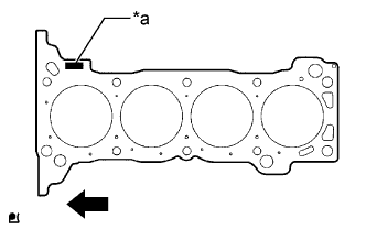
Обозначения на рисунке *a Номер партии Передняя сторона двигателя Поместите прокладку на поверхность блока цилиндров таким образом, чтобы штамп с номером партии был обращен вверх.
Note
-
Удалите все масло с контактной поверхности.
-
Убедитесь, что прокладка установлена с соблюдением ориентации.
-
-
-
INSTALL CYLINDER HEAD SUB-ASSEMBLY
Tech Tips
-
Выполните "Послеремонтную проверку" после замены головки блока цилиндров в сборе (см. стр. Click here).
-
Установочные болты крепления головки блока цилиндров затягиваются в 3 последовательных этапа.
-
Установите головку блока цилиндров в сборе на блок цилиндров.
Note
-
Убедитесь в отсутствии масла на установочной поверхности головки блока цилиндров.
-
Устанавливайте головку блока цилиндров осторожно, чтобы не повредить прокладку нижней частью головки.
-
-
Поместите под установочные болты головки блока цилиндров плоские шайбы.
-
Нанесите тонкий слой моторного масла на резьбы и под головки установочных болтов головки блока цилиндров.
-
Шаг 1:
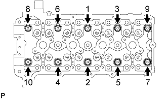
В несколько этапов вверните и равномерно затяните 10 установочных болтов головки блока цилиндров с плоскими шайбами. Последовательность затяжки показана на рисунке.
- Torque:
- 39 Н*м { 398 кгс*см, 29 фунт-сила-футов }
-
Отметьте краской переднюю сторону головки каждого установочного болта головки блока цилиндров.
-
Шаг 2:
Затяните установочные болты головки блока цилиндров на 90° в той же последовательности, что и на шаге 1.
-
Шаг 3:
Затяните установочные болты головки блока цилиндров с поворотом на 90° в той же последовательности, что и на шаге 1.
-
Убедитесь, что метки развернуты на 180° относительно исходного положения.
-
-
INSTALL CAMSHAFT TIMING EXHAUST GEAR ASSEMBLY
Tech Tips
Perform "Inspection After Repairs" after replacing the camshaft timing exhaust gear assembly Click here.
-
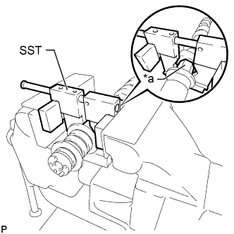
Text in Illustration *a Hexagonal Portion Using SST, grip the hexagonal portion, and then secure the SST and No. 2 camshaft in a vise as shown in the illustration.
- SST
- 09212-31010
Note
-
Do not damage the No. 2 camshaft.
-
Never grip areas other than the hexagonal portion, as this may cause damage.
-
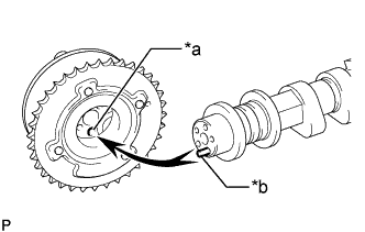
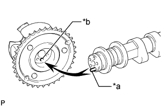
Text in Illustration *a Straight Pin Hole *b Straight Pin Align and attach the straight pin of the No. 2 camshaft with the straight pin hole of the camshaft timing exhaust gear assembly.
-
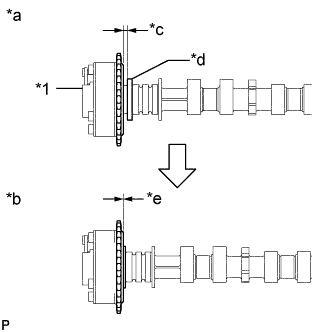
Text in Illustration *1 Camshaft Timing Exhaust Gear Assembly *a INCORRECT *b CORRECT *c Clearance *d Camshaft Flange *e No Clearance Check that there is no clearance between the camshaft timing exhaust gear assembly and camshaft flange.
Note
Be sure not to remove the other 4 bolts. If removing the bolts, exchange the camshaft timing exhaust gear assembly.
-
Fix the camshaft timing exhaust gear assembly with the flange bolt.
- Torque:
- 78 N*m { 795 kgf*cm, 58 ft.*lbf }
-
-
INSTALL CAMSHAFT TIMING GEAR ASSEMBLY
Tech Tips
Perform "Inspection After Repairs" after replacing the camshaft timing gear assembly Click here.
-
Text in Illustration *a Hexagonal Portion Using SST, grip the hexagonal portion, and then secure the SST and camshaft in a vise as shown in the illustration.
- SST
- 09212-31010
Note
-
Do not damage the camshaft.
-
Never grip areas other than the hexagonal portion, as this may cause damage.
-
Text in Illustration *a Straight Pin *b Straight Pin Hole Align the straight pin hole and straight pin and install the camshaft timing gear assembly to the camshaft.
-
Lightly press the gear against the camshaft and turn the gear. Push further at the position where the straight pin enters the straight pin hole.
Note
Be sure not to turn the camshaft timing gear assembly in the retard direction (the right angle).
-
Text in Illustration *1 Camshaft Timing Gear Assembly *a INCORRECT *b CORRECT *c Clearance *d Camshaft Flange *e No Clearance Check that there is no clearance between the camshaft timing gear assembly and the flange of the camshaft.
Note
-
Since the thrust clearance of the camshaft is small, the camshaft must be kept level while it is being removed. If the camshaft is not kept level, the portion of the cylinder head receiving the shaft thrust may crack or be damaged, causing the camshaft to seize or break.
-
Be sure not to remove the other 3 bolts. If removing the bolts, exchange the camshaft timing gear assembly.
-
-
With the camshaft timing gear assembly fixed in place, install the flange bolt.
- Torque:
- 78 N*m { 795 kgf*cm, 58 ft.*lbf }
-
Check that the camshaft timing gear assembly can move in the retard direction (the right angle), and is locked at the most retarded position.
-
-
INSTALL VALVE LASH ADJUSTER ASSEMBLY
-
Перед установкой каждого механизма регулировки зазора в приводе клапана обязательно проверяйте его (см. стр. Click here).
-
Установите 16 механизмов регулировки зазора в приводе клапана на головку блока цилиндров.
Note
Устанавливайте каждый механизм регулировки зазора в приводе клапана на то же место, откуда он снимался.
-
-
INSTALL VALVE STEM CAP
-
Нанесите тонкий слой моторного масла на торцы штока клапана.
-
Установите 16 колпачков штоков клапанов на головку блока цилиндров.
Note
Будьте осторожны, чтобы не уронить колпаки штоков клапанов в головку блока цилиндров.
-
-
INSTALL NO. 1 VALVE ROCKER ARM SUB-ASSEMBLY
-
Нанесите слой чистого моторного масла на выступы механизма регулировки зазора в приводе клапана и поверхности колпака штока клапана.
-
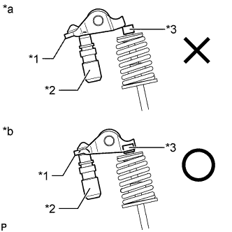
Обозначения на рисунке *1 Рычаг привода клапана № 1 *2 Механизм регулировки зазора в приводе клапана в сборе *3 Колпак штока клапана *a НЕПРАВИЛЬНО *b ПРАВИЛЬНО Установите 16 рычагов привода клапанов № 1, как показано на рисунке.
Note
Установите крышку штока клапана, механизм регулировки зазора в приводе клапана в сборе и рычаг привода клапана № 1 в сборе в те же места, откуда они были сняты.
-
-
INSTALL CAMSHAFTS
Tech Tips
После замены распредвала или распредвала № 2 выполните процедуру "Проверка после ремонта" (см. стр. Click here).
-
Смажьте кулачки распредвала и шейки головки блока цилиндров чистым моторным маслом.
-
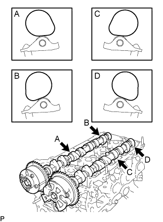
Установите распредвал и распредвал № 2, как показано на рисунке.
-
Обозначения на рисунке *1 Рычаг привода клапана № 1 *2 Механизм регулировки зазора в приводе клапана в сборе *3 Колпак штока клапана *a НЕПРАВИЛЬНО *b ПРАВИЛЬНО Убедитесь, что коромысла привода клапана № 1 установлены так, как показано на рисунке.
-
-
INSTALL CAMSHAFT BEARING CAP
-
Временно установите крышку подшипника распредвала № 1.
-
Проверьте положение каждой крышки подшипника распредвала № 2 и установите их в правильном положении.
-
Равномерно наживите 20 болтов, удерживая распредвал строго горизонтально.
-
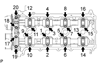
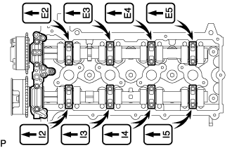
Затяните 20 болтов в порядке, указанном на рисунке.
- Torque:
- 16 Н*м { 158 кгс*см, 11 фунт-сила-футов }
-
-
INSTALL OIL JET
-
Install a new gasket and oil jet with the bolt.
- Torque:
- 21 N*m { 214 kgf*cm, 15 ft.*lbf }
-
-
INSTALL CRANKSHAFT PULLEY SET KEY
-
Install the 2 crankshaft pulley set keys to the crankshaft.
-
-
INSTALL CRANK POSITION SENSOR ROTOR
-
Text in Illustration *1 Crankshaft Pulley Set Key *a Front Mark *b Key Groove Install the crankshaft position sensor rotor with the front mark facing forward.
-
-
INSTALL NO. 1 CHAIN VIBRATION DAMPER
-
Установите успокоитель цепи № 1 и закрепите его 2 болтами.
- Torque:
- 21 Н*м { 214 кгс*см, 15 фунт-сила-футов }
-
-
INSTALL CHAIN SUB-ASSEMBLY
-
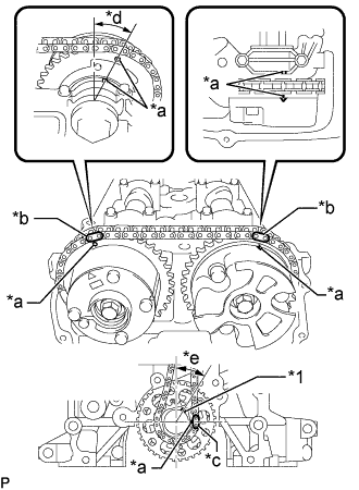
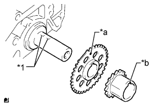
Обозначения на рисунке *1 Шпонка *a Установочная метка *b Пластина с меткой (желтая) *c Пластина с меткой (розовая) *d Примерно 13° *e Примерно 30° Как показано на рисунке, установите цепь в сборе на зубчатое колесо распредвала выпускных клапанов в сборе и зубчатое колесо распредвала в сборе, совместив пластины с метками с синхронизирующими метками на зубчатом колесе распредвала выпускных клапанов в сборе и зубчатом колесе распредвала в сборе.
Tech Tips
-
Пластина распредвала отмечена желтой краской.
-
Пластина коленчатого вала имеет розовую метку.
-
-
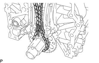
Закрепите цепь на ведущей звездочке или зубчатом колесе коленчатого вала с помощью веревки. Привяжите веревку рядом с ведущим зубчатым колесом или звездочкой коленчатого вала.
Note
После установки натяжителя цепи № 1 в сборе веревку необходимо снять.
Tech Tips
Веревка предотвращает перескакивание цепи через зубцы.
-
-
INSTALL CHAIN TENSIONER SLIPPER
-
Установите башмак натяжителя цепи и закрепите его болтом.
- Torque:
- 21 Н*м { 214 кгс*см, 15 фунт-сила-футов }
-
-
INSTALL NO. 1 CHAIN TENSIONER ASSEMBLY
-
Установите новую прокладку и натяжитель цепи № 1 в сборе, закрепив его болтом и гайкой.
- Torque:
- 10 Н*м { 102 кгс*см, 7 фунт-сила-футов }
Note
Снимите шестигранный ключ после установки направляющей цепного привода газораспределительного механизма.
-
-
INSTALL TIMING CHAIN GUIDE
-
Обозначения на рисунке *1 Кольцевое уплотнение Установите новое кольцевое уплотнение и направляющую цепного привода газораспределительного механизма, закрепив их 2 болтами.
- Torque:
- 10 Н*м { 102 кгс*см, 7 фунт-сила-футов }
-
-
CHECK NO. 1 CYLINDER TO TDC/COMPRESSION
-
Убедитесь, что цилиндр № 1 находится в ВМТ такта сжатия.
-
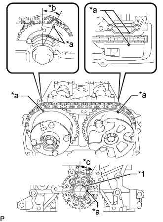
Обозначения на рисунке *1 Шпонка *a Установочная метка *b Примерно 13° *c Примерно 30° Поверните коленчатый вал на два полных оборота и убедитесь, что установочные метки совмещены, как показано на рисунке.
Если синхронизирующие метки не совпадают, заново установите цепь.
-
-
-
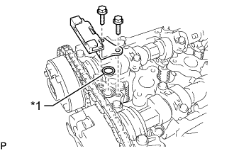
INSTALL CYLINDER HEAD COVER CONNECTOR SUB-ASSEMBLY
-
Установите новую прокладку масляного отверстия крышки подшипника распредвала № 2 и 3 новые прокладки масляного отверстия крышки подшипника распредвала № 3 в крышку подшипника распредвала.
-
Установите разъем крышки головки блока цилиндров и закрепите 2 болтами.
- Torque:
- 10 Н*м { 102 кгс*см, 7 фунт-сила-футов }
-
-
INSTALL TIMING CHAIN CASE OIL SEAL
-
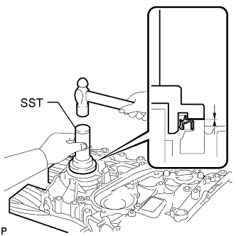
С помощью SST и молотка запрессуйте новый сальник картера цепного привода газораспределительного механизма так, чтобы его поверхность была заподлицо с краем крышки цепного или ременного привода газораспределительного механизма в сборе.
- SST
- 09223-75010
- 09950-70010 ( 09951-07100 )
Note
-
Не допускайте попадания на кромку посторонних материалов.
-
Проследите, чтобы сальник картера цепного привода газораспределительного механизма был запрессован без перекоса.
-
Нанесите универсальную консистентную смазку на кромку сальника картера цепного привода газораспределительного механизма.
-
-
INSTALL ENGINE WATER PUMP ASSEMBLY
-
Install a new gasket and the engine water pump assembly with the 8 bolts.
- Torque:
- 8.9 N*m { 91 kgf*cm, 79 in.*lbf }
-
-
INSTALL TIMING CHAIN OR BELT COVER SUB-ASSEMBLY
-
Удалите остатки старого герметика (FIPG). Следите за тем, чтобы масло не попало на контактные поверхности крышки цепного или ременного привода газораспределительного механизма и блока цилиндров.
-
Установите 3 новых кольцевых уплотнения в крышку цепного или ременного привода газораспределительного механизма.
-
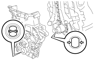
Совместите соединительную часть ведущей шестерни масляного насоса и ведущего зубчатого колеса коленчатого вала, а затем установите крышку цепного или ременного привода газораспределительного механизма в сборе.
-
Нанесите герметик, как показано на рисунке.
Обозначения на рисунке *1 Головка блока цилиндров в сборе *2 Блок цилиндров в сборе *a 2,0 мм (0,0787 дюйма) *b 2,5 мм (0,0984 дюйма) *c 3,0 мм (0,118 дюйма) *d 5,0 мм (0,197 дюйма) *e 6,0 мм (0,236 дюйма) *f 7,0 мм (0,276 дюйма) *g 8,0 мм (0,315 дюйма) или более *h 20 мм (0,787 дюйма) *i 42 мм (1,65 дюйма) *j 43 мм (1,69 дюйма) *k 56,5 мм (2,22 дюйма) *l 2,5 - 4,0 мм (0,0984 - 0,157 дюйма) *m 5,0 - 6,0 мм (0,197 - 0,236 дюйма) *n 9,0 - 13 мм (0,354 - 0,512 дюйма) *o 10 - 14 мм (0,394 - 0,551 дюйма) *p 12 - 16 мм (0,472 - 0,630 дюйма) *q Герметик - - Герметик Фирменный герметик Seal Packing Black от компании Toyota, Three bond 1207B или аналогичный Note
-
Если контактные поверхности влажные, перед нанесением герметика протрите их тканью, не содержащей масла.
-
После нанесения герметика в течение 3 минут установите крышку цепного или ременного привода газораспределительного механизма в сборе и в течение 15 минут затяните болты.
-
Не заливайте моторное масло в течение, как минимум, 4 часов после установки.
-
Не запускайте двигатель в течение 4 часов после установки.
-
-
Установите крышку цепного или ременного привода газораспределительного механизма в сборе, наживите 16 болтов и гайку, а затем затяните их в порядке, указанном на рисунке.
Обозначения на рисунке *a Типы гаек и болтов *b Порядок затяжки Болт 
Гайка - Torque:
- для болта A
- 57 Н*м { 581 кгс*см, 42 фунт-сила-фута }
- для болта B и гайки
- 23 Н*м { 235 кгс*см, 17 фунт-сила-футов }
- Для болта C
- 21 Н*м { 214 кгс*см, 15 фунт-сила-футов }
- Для болта D
- 25 Н*м { 255 кгс*см, 18 фунт-сила-футов }
Длина болта Параметр Длина Диаметр резьбы Болт A 75 мм (2,95 дюйма) 10 мм (0,394 дюйма) болт B 75 мм (2,95 дюйма) 8,0 мм (0,315 дюйма) Болт C 40 мм (1,57 дюйма) 8,0 мм (0,315 дюйма) Болт D 90 мм (3,54 дюйма) 8,0 мм (0,315 дюйма) -
Удалите герметик из 2 болтовых отверстий для кронштейна опоры компрессора № 1.
Note
Не используйте для удаления герметика какие-либо очистители.
-
-
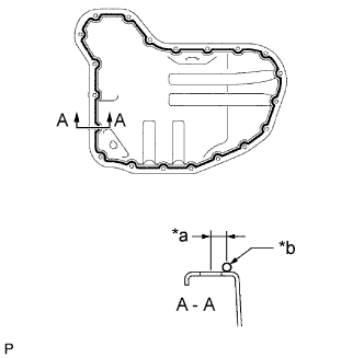
INSTALL OIL STRAINER SUB-ASSEMBLY
-
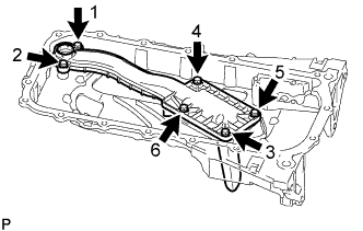
Install the oil strainer sub-assembly with the 6 bolts, and tighten the 6 bolts in the sequence shown in the illustration.
- Torque:
- 10 N*m { 102 kgf*cm, 7 ft.*lbf }
-
-
INSTALL OIL PAN SUB-ASSEMBLY
-
Вверните шпильку.
-
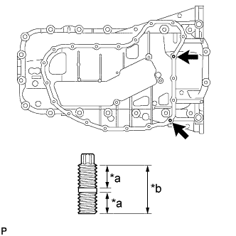
Обозначения на рисунке *a 9,0 мм (0,354 дюйма) *b 19,0 мм (0,748 дюйма) С помощью торцевого ключа "TORX" Е6 вверните резьбовые шпильки.
- Torque:
- 3,0 Н*м { 31 кгс*см, 27 фунт-сила-дюймов }
-
-
Аккуратно удалите остатки старого герметика (FIPG). Следите за тем, чтобы масло не попало на контактные поверхности блока цилиндров и поддона картера.
-
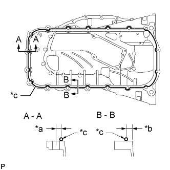
Обозначения на рисунке *a 8,0 мм (0,315 дюйма) *b 6,5 мм (0,256 дюйма) *c Герметик Нанесите герметик, как показано на рисунке.
Герметик Фирменный герметик Seal Packing Black от компании Toyota, Three bond 1207B или аналогичный Номинальный диаметр уплотнения 2,0 - 3,0 мм (0,0787 - 0,118 дюйма) Note
-
После нанесения герметика в течение 3 минут установите масляный поддон и в течение 15 минут затяните болты.
-
Не заливайте моторное масло в течение, как минимум, 4 часов после установки.
-
Не запускайте двигатель в течение 4 часов после установки.
-
-
Установите новую прокладку на маслоприемник с сетчатым фильтром в сборе.
-
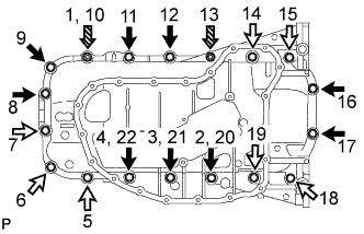
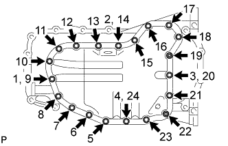
Установите масляный поддон в сборе, наживите 16 болтов и 2 гайки, а затем затяните их в порядке, указанном на рисунке.
- Torque:
- 26 Н*м { 265 кгс*см, 19 фунт-сила-футов }
Длина болта Параметр / Устройство Длина Болт A 20 мм (0,787 дюйма) болт B 40 мм (1,57 дюйма) Обозначения на рисунке Болт A болт B 
Гайка
-
-
INSTALL NO. 2 OIL PAN SUB-ASSEMBLY
-
Аккуратно удалите остатки старого герметика (FIPG). Следите за тем, чтобы масло не попало на контактные поверхности масляного поддона в сборе и масляного поддона № 2 в сборе.
-
Обозначения на рисунке *a 6,0 мм (0,236 дюйма) *b Герметик Нанесите герметик, как показано на рисунке.
Герметик Фирменный герметик Seal Packing Black от компании Toyota, Three bond 1207B или аналогичный Номинальный диаметр уплотнения 3,0 - 4,0 мм (0,118 - 0,157 дюйма) Note
-
Масляный поддон № 2 устанавливается в течение 3 мин, а болты затягиваются в течение 15 мин после нанесения герметика.
-
Не заливайте моторное масло в течение, как минимум, 4 часов после установки.
-
Не запускайте двигатель в течение 4 часов после установки.
-
-
Установите масляный поддон № 2 в сборе, наживите 18 болтов и 2 гайки, а затем затяните их в порядке, указанном на рисунке.
- Torque:
- 9,0 Н*м { 92 кгс*см, 80 фунт-сила-дюймов }
-
Установите новую прокладку и пробку сливного отверстия масляного поддона.
- Torque:
- 38 Н*м { 382 кгс*см, 28 фунт-сила-дюймов }
-
-
INSTALL CRANKSHAFT PULLEY
-
Совместите шпоночную канавку шкива коленчатого вала с установочной шпонкой и установите шкив.
-
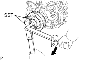
С помощью SST зафиксируйте шкив коленчатого вала на месте и затяните новый установочный болт шкива коленчатого вала.
- SST
- 09213-54015 ( 91651-60855 )
- 09330-00021
- Torque:
- 260 Н*м { 2651 кгс*см, 192 фунт-сила-фута }
Note
Повторное использование установочного болта шкива коленчатого вала запрещено.
-
-
INSTALL NO. 1 VENTILATION CONNECTOR
-
Install the No. 1 ventilation connector to the cylinder head cover sub-assembly with the 2 bolts.
- Torque:
- 9.0 N*m { 92 kgf*cm, 80 in.*lbf }
-
-
INSTALL CYLINDER HEAD COVER SUB-ASSEMBLY
-
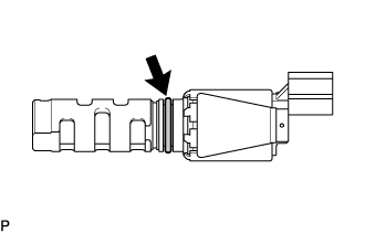
INSTALL CAMSHAFT TIMING OIL CONTROL VALVE ASSEMBLY
-
for Intake Side:
-
Apply a light coat of engine oil to the a new O-ring, and install it to the camshaft timing oil control valve assembly.
Note
Do not damage the O-ring when installing.
Tech Tips
An O-ring is already installed in a new camshaft timing oil control valve assembly. So, the O-ring only needs to be coated with engine oil when the assembly is replaced with a new one.
-
Install the camshaft timing oil control valve assembly to the cylinder head sub-assembly with the bolt.
- Torque:
- 9.0 N*m { 92 kgf*cm, 80 in.*lbf }
Note
-
Replace with a new part if it is dropped or if it receives a strong impact.
-
Make sure that the O-ring is not cracked or jammed when installing.
-
Connect the camshaft timing oil control valve connector.
-
-
for Exhaust Side:
-
Apply a light coat of engine oil to the a new O-ring, and install it to the camshaft timing oil control valve assembly.
Note
Do not damage the O-ring when installing.
Tech Tips
An O-ring is already installed in a new camshaft timing oil control valve assembly. So, the O-ring only needs to be coated with engine oil when the assembly is replaced with a new one.
-
Install the camshaft timing oil control valve assembly to the cylinder head cover sub-assembly with the bolt.
- Torque:
- 9.0 N*m { 92 kgf*cm, 80 in.*lbf }
Note
-
Replace with a new part if it is dropped or if it receives a strong impact.
-
Make sure that the O-ring is not cracked or jammed when installing.
-
Connect the camshaft timing oil control valve connector.
-
-
-
INSTALL CRANKSHAFT POSITION SENSOR
-
Apply a light coat of engine oil to the O-ring of the crankshaft position sensor.
-
Install the crankshaft position sensor with the bolt.
- Torque:
- 8.5 N*m { 87 kgf*cm, 75 in.*lbf }
Note
-
When reusing the crankshaft position sensor, inspect the O-ring.
-
Make sure that the O-ring is not cracked or jammed when installing the crankshaft position sensor.
-
Connect the crankshaft position sensor connector and attach the 2 wire harness clamps.
-
-
INSTALL CAMSHAFT POSITION SENSOR
-
for Intake Side:
-
Apply a light coat of engine oil to the O-ring of the camshaft position sensor.
-
Install the camshaft position sensor with the bolt.
- Torque:
- 9.0 N*m { 92 kgf*cm, 80 in.*lbf }
Note
-
When reusing the camshaft position sensor, inspect the O-ring.
-
Make sure that the O-ring is not cracked or jammed when installing the camshaft position sensor.
-
Connect the camshaft position sensor connector.
-
-
for Exhaust Side:
-
Apply a light coat of engine oil to the O-ring of the camshaft position sensor.
-
Install the camshaft position sensor with the bolt.
- Torque:
- 9.0 N*m { 92 kgf*cm, 80 in.*lbf }
Note
-
When reusing the camshaft position sensor, inspect the O-ring.
-
Make sure that the O-ring is not cracked or jammed when installing the camshaft position sensor.
-
Connect the camshaft position sensor connector.
-
-
-
INSTALL PCV VALVE SUB-ASSEMBLY
-
Text in Illustration *1 O-Ring Apply a light coat of engine oil to the O-ring.
-
Install the PCV valve sub-assembly.
- Torque:
- 5.0 N*m { 51 kgf*cm, 44 in.*lbf }
Tech Tips
When reusing the PCV valve sub-assembly, inspect the O-ring.
If the O-ring has scratches or cuts, replace the PCV valve sub-assembly.
-
Connect the PCV hose to the PCV valve sub-assembly, and slide the clamp to secure the hose.
-
-
INSTALL OIL FILLER CAP SUB-ASSEMBLY