NAVIGATION SYSTEM Speaker Circuit
| DTC Code | DTC Name |
|---|---|
| Speaker Circuit |
DESCRIPTION
The sound signals amplified by the radio and display receiver assembly are sent to the speakers from the radio and display receiver assembly via the speaker circuit.
If there is a short in a speaker circuit, the radio and display receiver assembly detects it and stops output to the speakers.
Thus sound cannot be heard from the speakers even if there is no malfunction in the radio and display receiver assembly, telematics transceiver* or speakers.
*: w/ Telematics Transceiver
WIRING DIAGRAM
CAUTION / NOTICE / HINT
Check that the wire harness is properly installed and does not have any sharp bends, pinching or loose connections.
PROCEDURE
CHECK VEHICLE CONDITION
Check the vehicle condition.
Result
Result
Proceed to
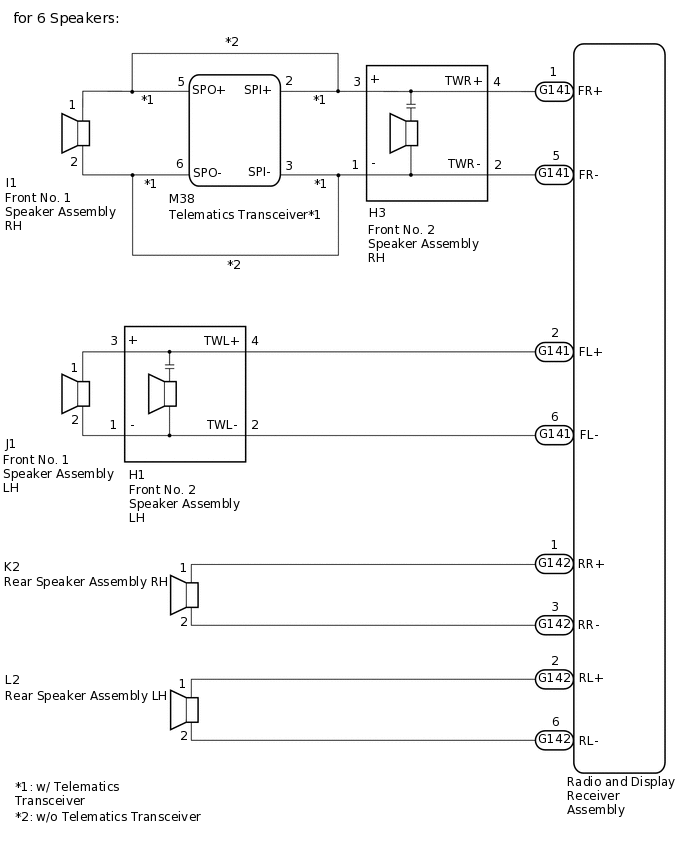
for 6 Speakers (w/ Telematics Transceiver)
A
for 6 Speakers (w/o Telematics Transceiver)
B
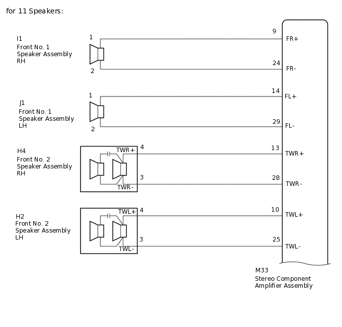
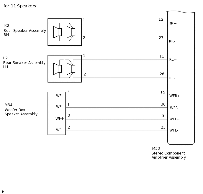
for 11 Speakers
C
B CHECK HARNESS AND CONNECTOR (SPEAKER CIRCUIT)Click here
C CHECK HARNESS AND CONNECTOR (SPEAKER CIRCUIT)Click here
CHECK HARNESS AND CONNECTOR (SPEAKER CIRCUIT)
*1: for LH Side
*2: for RH Side
Disconnect the G141 and G142 radio and display receiver assembly connectors.
Disconnect the J1*1 and/or I1*2 front No. 1 speaker assembly connector.
Disconnect the H1*1 and/or H3*2 front No. 2 speaker assembly connector.
Disconnect the L2*1 and/or K2*2 rear speaker assembly connector.
Disconnect the M38 telematics transceiver connector.
Measure the resistance according to the value(s) in the table below.
Standard Resistance
Table 1. for LH Side Tester Connection
Condition
Specified Condition
G141-2 (FL+) - H1-4 (TWL+)
Always
Below 1 Ω
G141-6 (FL-) - H1-2 (TWL-)
Always
Below 1 Ω
H1-3 (+) - J1-1
Always
Below 1 Ω
H1-1 (-) - J1-2
Always
Below 1 Ω
G142-2 (RL+) - L2-1
Always
Below 1 Ω
G142-6 (RL-) - L2-2
Always
Below 1 Ω
G141-2 (FL+) - Body ground
Always
10 kΩ or higher
G141-6 (FL-) - Body ground
Always
10 kΩ or higher
G142-2 (RL+) - Body ground
Always
10 kΩ or higher
G142-6 (RL-) - Body ground
Always
10 kΩ or higher
H1-3 (+) - Body ground
Always
10 kΩ or higher
H1-1 (-) - Body ground
Always
10 kΩ or higher
Table 2. for RH Side Tester Connection
Condition
Specified Condition
G141-1 (FR+) - H3-4 (TWR+)
Always
Below 1 Ω
G141-5 (FR-) - H3-2 (TWR-)
Always
Below 1 Ω
H3-3 (+) - M38-2 (SPI+)
Always
Below 1 Ω
H3-1 (-) - M38-3 (SPI-)
Always
Below 1 Ω
M38-5 (SPO+) - I1-1
Always
Below 1 Ω
M38-6 (SPO-) - I1-2
Always
Below 1 Ω
G142-1 (RR+) - K2-1
Always
Below 1 Ω
G142-3 (RR-) - K2-2
Always
Below 1 Ω
G141-1 (FR+) - Body ground
Always
10 kΩ or higher
G141-5 (FR-) - Body ground
Always
10 kΩ or higher
M38-5 (SPO+) - Body ground
Always
10 kΩ or higher
M38-6 (SPO-) - Body ground
Always
10 kΩ or higher
G142-1 (RR+) - Body ground
Always
10 kΩ or higher
G142-3 (RR-) - Body ground
Always
10 kΩ or higher
H3-3 (+) - Body ground
Always
10 kΩ or higher
H3-1 (-) - Body ground
Always
10 kΩ or higher
Result
Proceed to
OK
NG
NG REPAIR OR REPLACE HARNESS OR CONNECTOR
INSPECT TELEMATICS TRANSCEIVER
Remove the telematics transceiver.
-
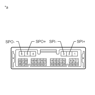
*a
Component without harness connected
(Telematics Transceiver)
Measure the resistance according to the value(s) in the table below.
Standard Resistance
Tester Connection
Condition
Specified Condition
2 (SPI+) - 5 (SPO+)
Always
Below 1 Ω
3 (SPI-) - 6 (SPO-)
Always
Below 1 Ω
2 (SPI+) - 3 (SPI-)
Always
10 kΩ or higher
5 (SPO+) - 6 (SPO-)
Always
10 kΩ or higher
2 (SPI+) or 5 (SPO+) - Body ground
Always
10 kΩ or higher
3 (SPI-) or 6 (SPO-) - Body ground
Always
10 kΩ or higher
Result
Proceed to
OK
NG
OK INSPECT FRONT NO. 1 SPEAKER ASSEMBLYClick here
CHECK HARNESS AND CONNECTOR (SPEAKER CIRCUIT)
*1: for LH Side
*2: for RH Side
Disconnect the G141 and G142 radio and display receiver assembly connectors.
Disconnect the J1*1 and/or I1*2 front No. 1 speaker assembly connector.
Disconnect the H1*1 and/or H3*2 front No. 2 speaker assembly connector.
Disconnect the L2*1 and/or K2*2 rear speaker assembly connector.
Measure the resistance according to the value(s) in the table below.
Standard Resistance
Table 3. for LH Side Tester Connection
Condition
Specified Condition
G141-2 (FL+) - H1-4 (TWL+)
Always
Below 1 Ω
G141-6 (FL-) - H1-2 (TWL-)
Always
Below 1 Ω
H1-3 (+) - J1-1
Always
Below 1 Ω
H1-1 (-) - J1-2
Always
Below 1 Ω
G142-2 (RL+) - L2-1
Always
Below 1 Ω
G142-6 (RL-) - L2-2
Always
Below 1 Ω
G141-2 (FL+) - Body ground
Always
10 kΩ or higher
G141-6 (FL-) - Body ground
Always
10 kΩ or higher
G142-2 (RL+) - Body ground
Always
10 kΩ or higher
G142-6 (RL-) - Body ground
Always
10 kΩ or higher
H1-3 (+) - Body ground
Always
10 kΩ or higher
H1-1 (-) - Body ground
Always
10 kΩ or higher
Table 4. for RH Side Tester Connection
Condition
Specified Condition
G141-1 (FR+) - H3-4 (TWR+)
Always
Below 1 Ω
G141-5 (FR-) - H3-2 (TWR-)
Always
Below 1 Ω
H3-3 (+) - I1-1
Always
Below 1 Ω
H3-1 (-) - I1-2
Always
Below 1 Ω
G142-1 (RR+) - K2-1
Always
Below 1 Ω
G142-3 (RR-) - K2-2
Always
Below 1 Ω
G141-1 (FR+) - Body ground
Always
10 kΩ or higher
G141-5 (FR-) - Body ground
Always
10 kΩ or higher
G142-1 (RR+) - Body ground
Always
10 kΩ or higher
G142-3 (RR-) - Body ground
Always
10 kΩ or higher
H3-3 (+) - Body ground
Always
10 kΩ or higher
H3-1 (-) - Body ground
Always
10 kΩ or higher
Result
Proceed to
OK
NG
NG REPAIR OR REPLACE HARNESS OR CONNECTOR
INSPECT FRONT NO. 1 SPEAKER ASSEMBLY
Remove the front No. 1 speaker assembly connector.
Inspect the front No. 1 speaker assembly.
Result
Proceed to
OK
NG
CHECK FRONT NO. 2 SPEAKER ASSEMBLY
Replace the front No. 2 speaker assembly with a new or known good one.
Check the malfunction disappears.
Tip:Connect all the connectors to the front No. 2 speaker assemblies that were disconnected.
When there is a possibility that either the right or left front speaker is defective, inspect by interchanging the right one with the left one.
Perform the above inspection on both LH and RH sides.
OK
Malfunction disappears.
Result
Proceed to
OK
NG
OK END (FRONT NO. 2 SPEAKER ASSEMBLY IS DEFECTIVE)
INSPECT REAR SPEAKER ASSEMBLY
Remove the rear speaker assembly connector.
Inspect the rear speaker assembly.
Result
Proceed to
OK
NG
CHECK HARNESS AND CONNECTOR (SPEAKER CIRCUIT)
*1: for LH Side
*2: for RH Side
Disconnect the M33 stereo component amplifier assembly connector.
Disconnect the J1*1 and/or I1*2 front No. 1 speaker assembly connector.
Disconnect the H2*1 and/or H4*2 front No. 2 speaker assembly connector.
Disconnect the L2*1 and/or K2*2 rear speaker assembly connector.
Disconnect the M34 Woofer box speaker assembly connector.
Measure the resistance according to the value(s) in the table below.
Standard Resistance
Table 5. for LH Side Tester Connection
Condition
Specified Condition
M33-14 (FL+) - J1-1
Always
Below 1 Ω
M33-29 (FL-) - J1-2
Always
Below 1 Ω
M33-10 (TWL+) - H2-4(TWL+)
Always
Below 1 Ω
M33-25 (TWL-) - H2-3(TWL-)
Always
Below 1 Ω
M33-11 (RL+) - L2-1
Always
Below 1 Ω
M33-26 (RL-) - L2-2
Always
Below 1 Ω
M33-14 (FL+) - Body ground
Always
10 kΩ or higher
M33-29 (FL-) - Body ground
Always
10 kΩ or higher
M33-10 (TWL+) - Body ground
Always
10 kΩ or higher
M33-25 (TWL-) - Body ground
Always
10 kΩ or higher
M33-11 (RL+) - Body ground
Always
10 kΩ or higher
M33-26 (RL-) - Body ground
Always
10 kΩ or higher
Table 6. for RH Side Tester Connection
Condition
Specified Condition
M33-9 (FR+) - I1-1
Always
Below 1 Ω
M33-24 (FR-) - I1-2
Always
Below 1 Ω
M33-13 (TWR+) - H4-4(TWR+)
Always
Below 1 Ω
M33-28 (TWR-) - H4-3(TWR-)
Always
Below 1 Ω
M33-12 (RR+) - K2-1
Always
Below 1 Ω
M33-27 (RR-) - K2-2
Always
Below 1 Ω
M33-9 (FR+) - Body ground
Always
10 kΩ or higher
M33-24 (FR-) - Body ground
Always
10 kΩ or higher
M33-13 (TWR+) - Body ground
Always
10 kΩ or higher
M33-28 (TWR-) - Body ground
Always
10 kΩ or higher
M33-12 (RR+) - Body ground
Always
10 kΩ or higher
M33-27 (RR-) - Body ground
Always
10 kΩ or higher
Table 7. for Woofer Box Speaker Tester Connection
Condition
Specified Condition
M33-15 (WFR+) - M34-4 (WF+)
Always
Below 1 Ω
M33-30 (WFR-) - M34-1 (WF-)
Always
Below 1 Ω
M33-8 (WFL+) - M34-3 (WF+)
Always
Below 1 Ω
M33-23 (WFL-) - M34-2 (WF-)
Always
Below 1 Ω
M33-15 (WFR+) - Body ground
Always
10 kΩ or higher
M33-30 (WFR-) - Body ground
Always
10 kΩ or higher
M33-8 (WFL+) - Body ground
Always
10 kΩ or higher
M33-23 (WFL-) - Body ground
Always
10 kΩ or higher
Result
Proceed to
OK
NG
NG REPAIR OR REPLACE HARNESS OR CONNECTOR
INSPECT FRONT NO. 1 SPEAKER ASSEMBLY
Remove the front No. 1 speaker assembly connector.
Inspect the front No. 1 speaker assembly.
Result
Proceed to
OK
NG
CHECK FRONT NO. 2 SPEAKER ASSEMBLY
Replace the front No. 2 speaker assembly with a new or known good one.
Check the malfunction disappears.
Tip:Connect all the connectors to the front No. 2 speaker assemblies that were disconnected.
When there is a possibility that either the right or left front speaker is defective, inspect by interchanging the right one with the left one.
Perform the above inspection on both LH and RH sides.
OK
Malfunction disappears.
Result
Proceed to
OK
NG
OK END (FRONT NO. 2 SPEAKER ASSEMBLY IS DEFECTIVE)
CHECK REAR SPEAKER ASSEMBLY
Replace the rear speaker assembly with a new or known good one.
Check the malfunction disappears.
Tip:Connect all the connectors to the rear speaker assemblies that were disconnected.
When there is a possibility that either the right or left front speaker is defective, inspect by interchanging the right one with the left one.
Perform the above inspection on both LH and RH sides.
OK
Malfunction disappears.
Result
Proceed to
OK
NG
OK END (REAR SPEAKER ASSEMBLY IS DEFECTIVE)
INSPECT WOOFER BOX SPEAKER ASSEMBLY
Remove the woofer box speaker assembly.
Inspect the woofer box speaker assembly.
Result
Proceed to
OK
NG
CHECK STEREO COMPONENT AMPLIFIER ASSEMBLY
Replace the stereo component amplifier assembly with a new or known good one.
Check the malfunction disappears.
OK
Malfunction disappears.
Result
Proceed to
OK
NG
OK END (STEREO COMPONENT AMPLIFIER ASSEMBLY IS DEFECTIVE)