INTAKE MANIFOLD (for DPF) REMOVAL
Note
-
When replacing the injectors (including shuffling the injectors between the cylinders), common rail or cylinder head, it is necessary to replace the injection pipes with new ones.
-
When replacing the fuel supply pump, common rail, cylinder block, cylinder head, cylinder head gasket or timing gear case, it is necessary to replace the fuel inlet pipe with a new one.
-
After removing the injection pipes and fuel inlet pipe, clean them with a brush and compressed air.
-
DISCONNECT CABLE FROM NEGATIVE BATTERY TERMINAL
Note
When disconnecting the cable, some systems need to be initialized after the cable is reconnected Click here.
-
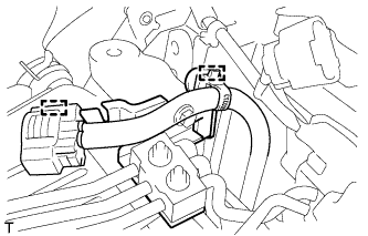
REMOVE INTAKE AIR CONNECTOR WITH ELECTRIC EGR CONTROL VALVE ASSEMBLY
-
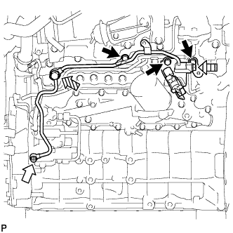
REMOVE NO. 4 INJECTION PIPE SUB-ASSEMBLY
-
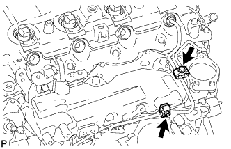
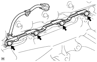
Remove the bolt, nut and 2 No. 2 injection pipe clamps.
-
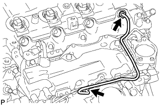
Using a 17 mm union nut wrench, loosen the union nuts and remove the No. 4 injection pipe.
-
-
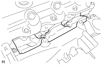
REMOVE WIRING HARNESS CLAMP BRACKET
-
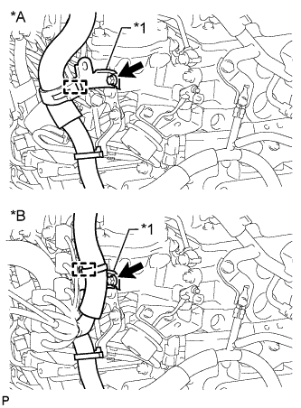
Text in Illustration *A for LHD *B for RHD *1 Wiring Harness Clamp Bracket Detach the wire harness clamp.
-
Remove the bolt and wiring harness clamp bracket.
-
-
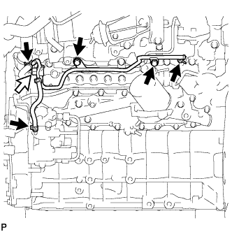
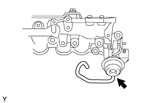
REMOVE NO. 2 FUEL PIPE
-
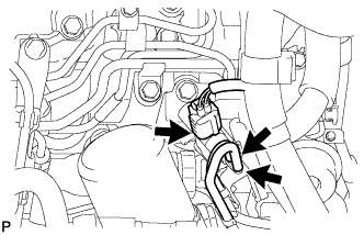
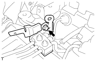
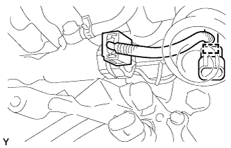
Disconnect the vacuum switching valve connector and 2 vacuum transmitting hoses.
-
Using a 6 mm hexagon wrench, remove the supply pump hollow screw and gasket.
Text in Illustration 
Bolt 
Supply Pump Hollow Screw 
Fuel Check Valve 
Union Bolt -
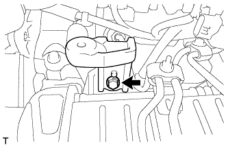
Remove the fuel check valve, union bolt and 2 gaskets.
-
Remove the 3 bolts and No. 2 fuel pipe.
-
-
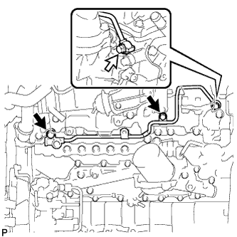
REMOVE NO. 3 NOZZLE LEAKAGE PIPE
-
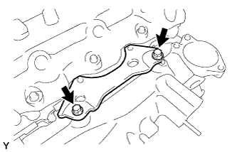
Disconnect the 3 fuel hoses.
Text in Illustration Fuel Check Valve -
Remove the 2 bolts.
-
Remove the fuel check valve, gasket and No. 3 nozzle leakage pipe.
-
-
REMOVE NO. 2 NOZZLE LEAKAGE PIPE ASSEMBLY
-
Remove the 2 bolts.
Text in Illustration Union Bolt -
Remove the union bolt, gasket and No. 2 nozzle leakage pipe.
-
-
REMOVE GLOW CONNECTOR BRACKET
-
Disconnect the No. 1 glow plug connector and detach the clamp.
-
Remove the bolt and glow connector bracket.
-
-
REMOVE NO. 3 INTERCOOLER SUPPORT BRACKET
-
Remove the bolt and No. 3 intercooler support bracket.
-
-
REMOVE NO. 2 MANIFOLD STAY
-
Remove the bolt and No. 2 manifold stay.
-
-
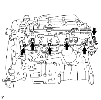
REMOVE NO. 1 GLOW PLUG CONNECTOR
-
Remove the 4 screw grommets.
-

Remove the 4 nuts and No. 1 glow plug connector.
-
-
REMOVE NO. 1 INTAKE MANIFOLD INSULATOR
-
REMOVE INTAKE MANIFOLD INSULATOR
-
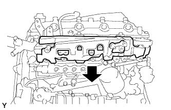
REMOVE INTAKE MANIFOLD
-
Disconnect the vacuum hose from the intake manifold.
-
Detach the sensor wire connector clamp from the intake manifold.
-
Remove the 4 bolts, 2 nuts, intake manifold and gasket.
-