GENERATOR DISASSEMBLY
PROCEDURE
REMOVE GENERATOR PULLEY CAP
-
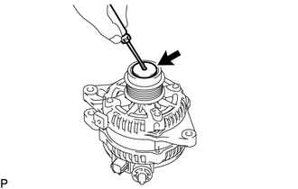
Using a screwdriver, puncture the center of the generator pulley cap and pry it off.
Note:Do not reuse the generator pulley cap.
-
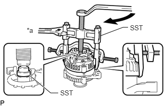
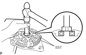
REMOVE GENERATOR PULLEY WITH CLUTCH
Mount the generator assembly in a vise between aluminum plates.
-
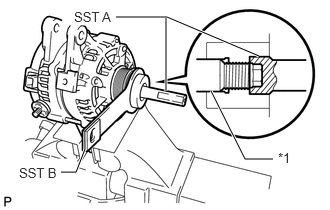
Install SST A and B to the generator pulley with clutch as shown in the illustration.
09820-63021
Table 1. Text in Illustration *1
Rotor Shaft
Note:Securely attach SST to the generator pulley with clutch and rotor shaft.
-
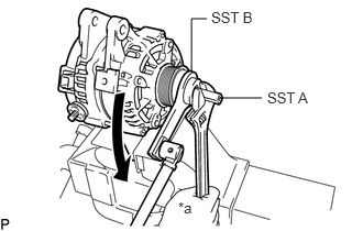
Using a wrench to hold SST A, turn SST B counterclockwise to loosen the generator pulley with clutch.
Table 2. Text in Illustration *a
Hold

Turn
Note:Be careful as the generator pulley with clutch or rotor shaft may be damaged if the position of SST is not securely maintained while performing this operation.
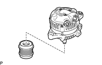
Remove SST from the generator assembly.
Remove the generator pulley with clutch from the rotor shaft.
REMOVE GENERATOR REAR END COVER
-
Place the generator assembly on the generator pulley with clutch.
-
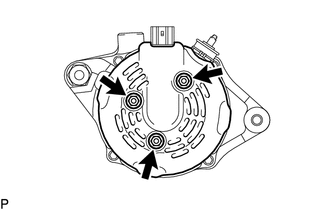
Remove the 3 bolts and generator rear end cover.
-
REMOVE TERMINAL INSULATOR
Remove the terminal insulator from the generator coil assembly.
REMOVE GENERATOR BRUSH HOLDER ASSEMBLY
-
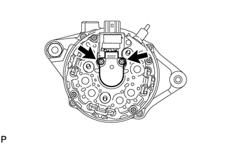
Remove the 2 screws and generator brush holder assembly from the generator coil assembly.
-
REMOVE GENERATOR COIL ASSEMBLY
-
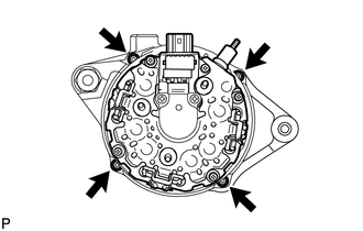
Remove the 4 bolts.
-
Using SST, remove the generator coil assembly.
09950-40011
09951-04020
09952-04010
09953-04020
09954-04010
09955-04071
09957-04010
09958-04011
Table 3. Text in Illustration *a
Hold
Turn
-
REMOVE BEARING COVER PACKING
-
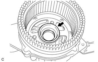
Remove the bearing cover packing.
Note:If the bearing cover packing breaks, remove all broken pieces.
Tip:The bearing cover packing may be installed on the generator rotor assembly.
-
REMOVE GENERATOR ROTOR ASSEMBLY
-
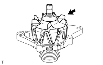
Remove the generator rotor assembly.
-
INSPECT GENERATOR DRIVE END FRAME BEARING
-
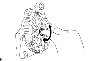
Check that the bearing is not rough or worn and that it rotates smoothly.
If necessary, replace the generator drive end frame bearing.
-
REMOVE GENERATOR DRIVE END FRAME BEARING
-
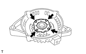
Remove the 4 screws and retainer plate from the generator drive end frame assembly.
-
Using SST and a hammer, tap out the generator drive end frame bearing from the generator drive end frame assembly.
09950-60010
09951-00250
09950-70010
09951-07100
-