REAR SUSPENSION MEMBER INSTALLATION
PROCEDURE
INSTALL REAR NO. 1 DIFFERENTIAL MOUNT CUSHION (for 4WD/AWD)
INSTALL REAR SUSPENSION MEMBER SUB-ASSEMBLY
-
*a
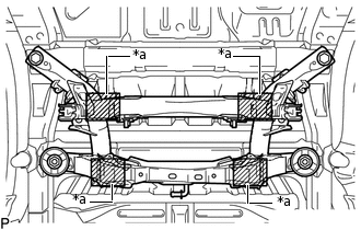
Attachment Placement Positions
Place wooden blocks or plate lift attachments on an engine lifter, and then set the rear suspension member sub-assembly so that the attachments are in the positions shown in the illustration.
Note:Place the wooden blocks or plate lift attachments so that the rear suspension member sub-assembly is level.
As the rear suspension member sub-assembly is very heavy, be sure to support it securely.
-
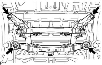
Install the rear suspension member and 2 rear upper body mounting cushions with the 2 bolts and 2 nuts.
125 N*m
1275 kgf*cm
92 ft.*lbf
-
INSTALL REAR DIFFERENTIAL CARRIER ASSEMBLY (for 4WD/AWD)
INSTALL PROPELLER WITH CENTER BEARING SHAFT ASSEMBLY (for 4WD/AWD)
TEMPORARILY INSTALL REAR UPPER CONTROL ARM ASSEMBLY LH
Temporarily install the upper control arm to the rear suspension member with the bolt and nut.
TEMPORARILY INSTALL REAR UPPER CONTROL ARM ASSEMBLY RH
Tip:Use the same procedure described for the LH side.
TEMPORARILY INSTALL REAR NO. 2 SUSPENSION ARM ASSEMBLY LH
TEMPORARILY INSTALL REAR NO. 2 SUSPENSION ARM ASSEMBLY RH
Tip:Use the same procedure described for the LH side.
INSTALL REAR LOWER COIL SPRING INSULATOR LH
INSTALL REAR LOWER COIL SPRING INSULATOR RH
Tip:Use the same procedure described for the LH side.
INSTALL REAR UPPER COIL SPRING INSULATOR LH
INSTALL REAR UPPER COIL SPRING INSULATOR RH
Tip:Use the same procedure described for the LH side.
INSTALL REAR COIL SPRING LH
INSTALL REAR COIL SPRING RH
Tip:Use the same procedure described for the LH side.
TEMPORARILY INSTALL REAR SHOCK ABSORBER ASSEMBLY LH
TEMPORARILY INSTALL REAR SHOCK ABSORBER ASSEMBLY RH
Tip:Use the same procedure described for the LH side.
INSTALL REAR AXLE CARRIER SUB-ASSEMBLY LH
Install the rear axle carrier to the rear upper control arm with the bolt and nut.
90 N*m
918 kgf*cm
66 ft.*lbf
Note:Since a stopper nut is used, tighten the bolt.
INSTALL REAR AXLE CARRIER SUB-ASSEMBLY RH
Tip:Use the same procedure described for the LH side.
TEMPORARILY INSTALL REAR NO. 1 SUSPENSION ARM ASSEMBLY LH
TEMPORARILY INSTALL REAR NO. 1 SUSPENSION ARM ASSEMBLY RH
Tip:Use the same procedure described for the LH side.
CONNECT REAR TRAILING ARM ASSEMBLY LH
Connect the rear trailing arm to the rear axle carrier with the 2 bolts.
200 N*m
2039 kgf*cm
148 ft.*lbf
CONNECT REAR TRAILING ARM ASSEMBLY RH
Tip:Use the same procedure described for the LH side.
INSTALL REAR STABILIZER BAR
INSTALL REAR STABILIZER LINK ASSEMBLY LH
INSTALL REAR STABILIZER LINK ASSEMBLY RH
Tip:Use the same procedure described for the LH side.
INSTALL REAR SUSPENSION MEMBER BRACE LH
INSTALL REAR SUSPENSION MEMBER BRACE RH
Tip:Use the same procedure described for the LH side.
INSTALL REAR AXLE HUB AND BEARING ASSEMBLY LH (for 2WD)
INSTALL REAR AXLE HUB AND BEARING ASSEMBLY RH (for 2WD)
Tip:Use the same procedure described for the LH side.
INSTALL REAR AXLE HUB AND BEARING ASSEMBLY LH (for 4WD/AWD)
INSTALL REAR AXLE HUB AND BEARING ASSEMBLY RH (for 4WD/AWD)
Tip:Use the same procedure described for the LH side.
INSTALL PARKING BRAKE ASSEMBLY
INSTALL REAR DISC
CONNECT REAR DISC BRAKE CALIPER ASSEMBLY LH
CONNECT REAR DISC BRAKE CALIPER ASSEMBLY RH
Tip:Use the same procedure described for the LH side.
CONNECT NO. 3 PARKING BRAKE CABLE ASSEMBLY
CONNECT NO. 2 PARKING BRAKE CABLE ASSEMBLY
Tip:Use the same procedure described for the No. 3 parking brake cable assembly.
CONNECT SKID CONTROL SENSOR WIRE LH (for 2WD)
CONNECT SKID CONTROL SENSOR WIRE RH (for 2WD)
Tip:Use the same procedure described for the LH side.
CONNECT REAR SPEED SENSOR LH (for 4WD/AWD)
CONNECT REAR SPEED SENSOR RH (for 4WD/AWD)
Tip:Use the same procedure described for the LH side.
INSTALL REAR AXLE SHAFT NUT LH (for 4WD/AWD)
INSTALL REAR AXLE SHAFT NUT RH (for 4WD/AWD)
Tip:Use the same procedure described for the LH side.
STABILIZE SUSPENSION
TIGHTEN REAR SHOCK ABSORBER ASSEMBLY LH
TIGHTEN REAR SHOCK ABSORBER ASSEMBLY RH
Tip:Use the same procedure described for the LH side.
TIGHTEN REAR UPPER CONTROL ARM ASSEMBLY LH
TIGHTEN REAR UPPER CONTROL ARM ASSEMBLY RH
Tip:Use the same procedure described for the LH side.
TIGHTEN REAR NO. 2 SUSPENSION ARM ASSEMBLY LH
TIGHTEN REAR NO. 2 SUSPENSION ARM ASSEMBLY RH
Tip:Use the same procedure described for the LH side.
TIGHTEN REAR NO. 1 SUSPENSION ARM ASSEMBLY LH
TIGHTEN REAR NO. 1 SUSPENSION ARM ASSEMBLY RH
Tip:Use the same procedure described for the LH side.
INSTALL REAR HEIGHT CONTROL SENSOR SUB-ASSEMBLY LH (w/ Automatic Headlight Beam Level Control System)
INSTALL REAR WHEEL
103 N*m
1050 kgf*cm
76 ft.*lbf
INSPECT AND ADJUST REAR WHEEL ALIGNMENT
ADJUST HEADLIGHT ASSEMBLY
INSPECT SPEED SENSOR SIGNAL
w/o VSC:Click here
w/ VSC:Click here