FRONT AIR CONDITIONING UNIT INSTALLATION
PROCEDURE
INSTALL AIR CONDITIONING UNIT ASSEMBLY
Note:Be sure to support the air conditioning unit assembly when installing it. Failure to do so may cause the bracket of the air conditioning unit assembly to break.
When installing the air conditioning unit assembly, eliminate static electricity by touching the vehicle body to prevent the components from being damaged.
Install the air conditioning unit assembly with the 4 nuts and bolt.
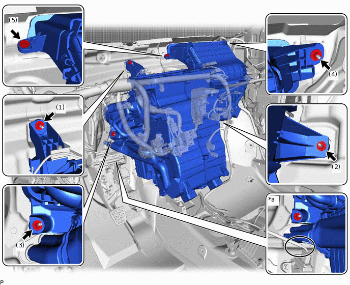
*a
Careful Point
-
-

Nut

Bolt
9.8 N*m
100 kgf*cm
87 in.*lbf
Note:Install the nuts and bolt in the order shown in the illustration.
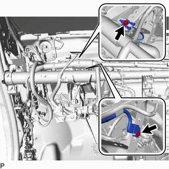
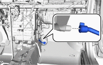
Be careful not to damage the pipes during installation.
Be careful not to damage the accelerator pedal connector (*a) during installation. (for LHD)
INSTALL INSTRUMENT PANEL REINFORCEMENT ASSEMBLY
Install the instrument panel reinforcement assembly with the 5 bolts as shown in the illustration.
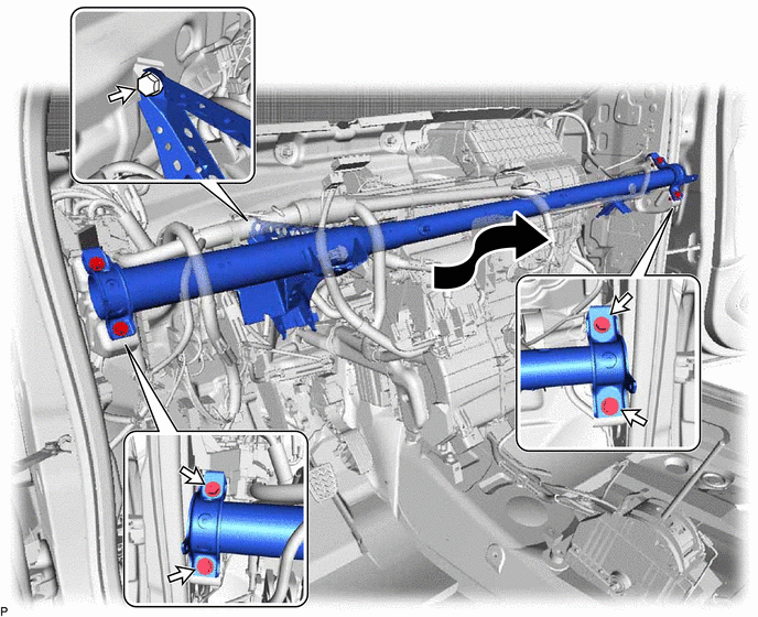
29 N*m
296 kgf*cm
21 ft.*lbf
Connect the connector.
Engage each clamp to the instrument panel reinforcement assembly.
-
Engage 2 clamps and connect the antenna cord sub-assembly.
-
Connect the 2 earth wires with the 2 bolts.
8.4 N*m
86 kgf*cm
74 in.*lbf
-
Install the driver side junction block assembly with the nut.
8.4 N*m
86 kgf*cm
74 in.*lbf
INSTALL CENTER INSTRUMENT PANEL TO COWL BRACE
-
Bolt
Nut
Install the center instrument panel to cowl brace with the bolt.
29 N*m
296 kgf*cm
21 ft.*lbf
Install the nut.
12 N*m
122 kgf*cm
9 ft.*lbf
-
INSTALL NO. 1 INSTRUMENT PANEL BRACE SUB-ASSEMBLY
-
Bolt (A)
Nut

Screw

Bolt (B)
Connect the earth wire with the bolt to the No. 1 instrument panel brace sub-assembly.
8.4 N*m
86 kgf*cm
74 in.*lbf
Install the No. 1 instrument panel brace sub-assembly with the nut, screw and bolt.
Nut
29 N*m
296 kgf*cm
21 ft.*lbf
Screw
1.2 N*m
12 kgf*cm
11 in.*lbf
Bolt
29 N*m
296 kgf*cm
21 ft.*lbf
Engage the clamp.
-
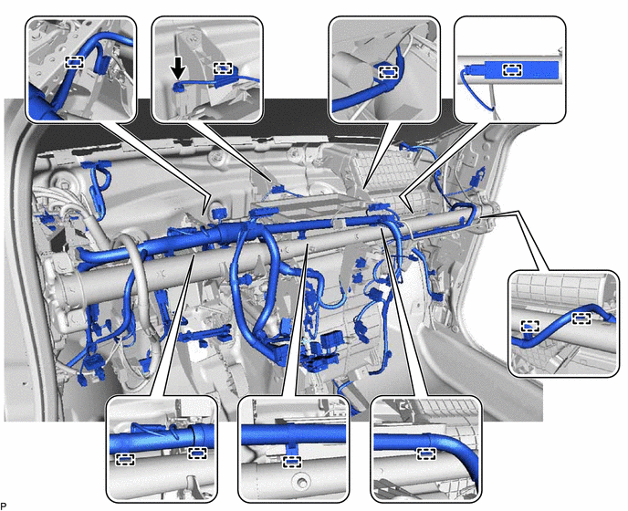
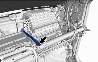
INSTALL DRAIN COOLER HOSE (w/ Cooler System)
-
Install the drain cooler hose as shown in the illustration.
-
INSTALL REAR NO. 1 AIR DUCT (w/ Rear Air Duct)
Engage the 2 claws to install the rear No. 1 air duct.
INSTALL REAR NO. 2 AIR DUCT (w/ Rear Air Duct)
Engage the 2 claws to install the rear No. 2 air duct.
INSTALL FRONT FLOOR CARPET ASSEMBLY (for RH Side)
-
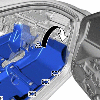
Install the front floor carpet assembly to the original position as shown in the illustration.
Engage the 3 guides.
Install the clip.
-
INSTALL FRONT FLOOR CARPET ASSEMBLY (for LH Side)
-
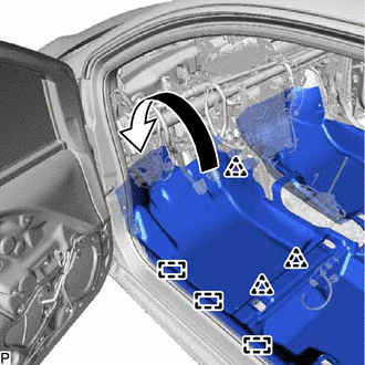
Install the front floor carpet assembly to the original position as shown in the illustration.
Engage the 3 guides.
Install the 3 clips.
-
INSTALL FRONT SEAT ASSEMBLY LH
INSTALL FRONT SEAT ASSEMBLY RH
INSTALL LOWER INSTRUMENT PANEL SUB-ASSEMBLY
INSTALL STEERING COLUMN ASSEMBLY
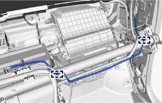
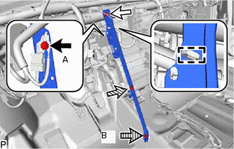
CONNECT OUTLET HEATER WATER HOSE
-
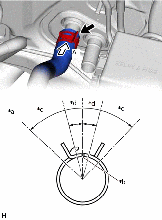
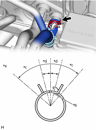
*a
View A
*b
Marking (White)
*c
Clip Installation Angle 45°
*d
Marking (White) Angle 15°
Connect the outlet heater water hose with the marking (white) facing up and engage the clip within the area shown in the illustration.
Note:Do not apply excessive force to the outlet heater water hose.
-
CONNECT INLET HEATER WATER HOSE
-
*a
View A
*b
Marking (White)
*c
Clip Installation Angle 45°
*d
Marking (White) Angle 15°
Connect the inlet heater water hose with the marking (white) facing up and engage the clip within the area shown in the illustration.
Note:Do not apply excessive force to the inlet heater water hose.
-
INSTALL COOLER EXPANSION VALVE (w/ Cooler System)
ADD ENGINE COOLANT
INSPECT FOR COOLANT LEAK
CHARGE AIR CONDITIONING SYSTEM WITH REFRIGERANT
WARM UP ENGINE
INSPECT FOR REFRIGERANT LEAK