WINDSHIELD DEICER SYSTEM TERMINALS OF ECU
-
CHECK AIR CONDITIONING AMPLIFIER ASSEMBLY
Figure 1. for 4 Zone Type:
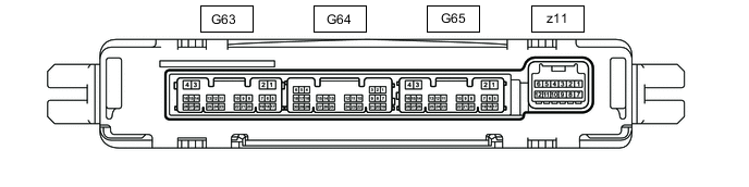
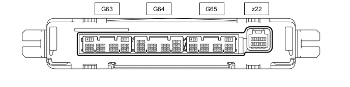
Figure 2. for Dual Type:
-
Disconnect the G65 air conditioning amplifier assembly connector.
-
Measure the voltage and resistance according to the value(s) in the table below.
Tester Connection Wiring Color Terminal Description Condition Specified Condition G65-2 (IG+) - Body ground LA-R - Body ground Power source (IG) Engine switch on (IG) 11 to 14 V Engine switch off Below 1 V G65-1 (+B1) - Body ground LA-W - Body ground Battery power supply Always 11 to 14 V G65-4 (GND) - Body ground LA - Body ground Ground Always Below 1 Ω -
Reconnect the G65 air conditioning amplifier assembly connector.
-
Measure the voltage according to the value(s) in the table below.
Tester Connection Wiring Color Terminal Description Condition Specified Condition G65-17 (FDEF) - Body ground GR - Body ground Windshield deicer signal Engine switch on (IG), windshield deicer switch off 11 to 14 V Engine switch on (IG), windshield deicer switch on Below 2.2 V
-