AIR CONDITIONING SYSTEM(for Automatic Air Conditioning System), Diagnostic DTC:B1422/22
| DTC Code | DTC Name |
|---|---|
| B1422/22 | Compressor Lock Sensor Circuit |
DESCRIPTION
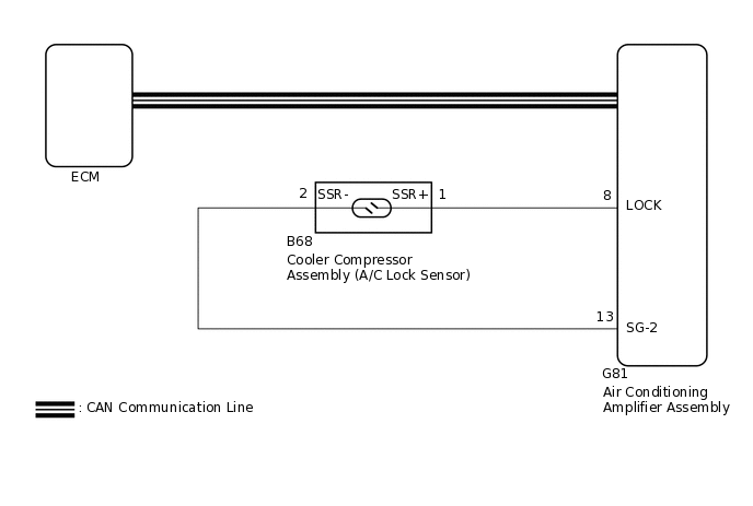
The ECM sends the engine speed signal to the air conditioning amplifier assembly via CAN communication.
The air conditioning amplifier assembly reads the difference between compressor speed and engine speed. When the difference becomes too large, the air conditioning amplifier assembly determines that the compressor is locked, and turns the magnet clutch off.
DTC No. |
Detection Item |
DTC Detection Condition |
Trouble Area |
Memory |
Note |
|---|---|---|---|---|---|
B1422/22 |
Compressor Lock Sensor Circuit |
Open or short in A/C lock sensor circuit |
|
- |
w/ Magnet Clutch |
The air conditioning amplifier assembly stores the DTC of the respective malfunction if it has occurred for the period of time indicated in the brackets.
WIRING DIAGRAM
CAUTION / NOTICE / HINT
Before performing the inspection, check that there are no problems related to the CAN communication system.
As DTC B1422/22 is also output when the compressor drive belt is damaged or loose, inspect the belt before performing troubleshooting.
PROCEDURE
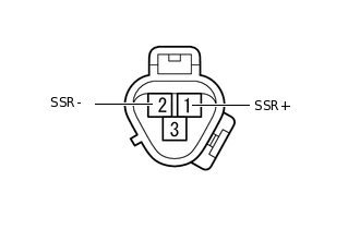
INSPECT COOLER COMPRESSOR ASSEMBLY (A/C LOCK SENSOR)
-
Remove the cooler compressor assembly.
Click here
Measure the resistance according to the value(s) in the table below.
Standard Resistance
Tester Connection
Condition
Specified Condition
1 (SSR+) - 2 (SSR-)
20°C (68°F)
160 to 320 Ω
Result
Proceed to
OK
NG
-
CHECK HARNESS AND CONNECTOR (AIR CONDITIONING AMPLIFIER ASSEMBLY - COOLER COMPRESSOR ASSEMBLY)
Disconnect the G81 air conditioning amplifier assembly connector.
Disconnect the B68 cooler compressor assembly (A/C lock sensor) connector.
Measure the resistance according to the value(s) in the table below.
Standard Resistance
Tester Connection
Condition
Specified Condition
G81-8 (LOCK) - B68-1 (SSR+)
Always
Below 1 Ω
G81-13 (SG-2) - B68-2 (SSR-)
Always
Below 1 Ω
G81-8 (LOCK) - Body ground
Always
10 kΩ or higher
G81-13 (SG-2) - Body ground
Always
10 kΩ or higher
Result
Result
Proceed to
OK (When troubleshooting according to the DTC)
A
OK (When troubleshooting according to Problem Symptoms Table)
B
NG
C
C REPAIR OR REPLACE HARNESS OR CONNECTOR