SFI SYSTEM MIL Circuit
| DTC Code | DTC Name |
|---|---|
| MIL Circuit |
DESCRIPTION
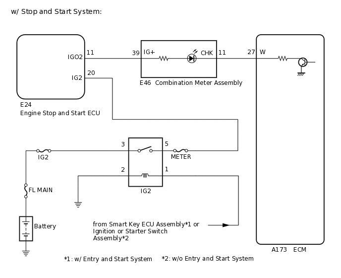
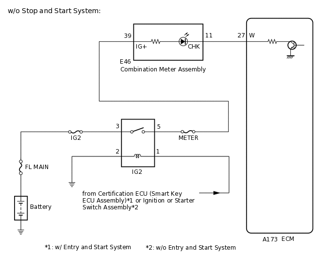
The MIL (Malfunction Indicator Lamp) is used to indicate vehicle malfunctions detected by the ECM. When the ignition switch is turned to ON, power is supplied to the MIL circuit, and the ECM provides the circuit ground which illuminates the MIL.
The MIL operation can be checked visually: When the ignition switch is turned to ON, the MIL should be illuminated and should turn off after engine is started. If the MIL remains illuminated or is not illuminated, conduct the following troubleshooting procedure using the GTS.
WIRING DIAGRAM
PROCEDURE
CHECK THAT MIL IS ILLUMINATED
Perform troubleshooting in accordance with the table below.
Result
Condition
Result
Proceed to
MIL remains ON
Ignition switch ON → engine is started
A
MIL does not illuminate
Ignition switch ON → engine is started (sometimes does not start)
B
MIL ON → MIL OFF
Ignition switch ON → engine is started
C
CHECK WHETHER DTC OUTPUT RECURS
Connect the GTS to the DLC3.
Turn the ignition switch to ON.
Turn the GTS on.
Enter the following menus: System Select / Health Check.
Read the DTCs using the GTS.
Result
Result
Proceed to
DTCs is output
A
DTCs are not output
B
Tip:Check for detected DTCs output from other ECUs which relate to the MIL.
A GO TO DTC CHART
CHECK HARNESS AND CONNECTOR (CHECK FOR SHORT IN WIRE HARNESS)
-
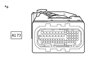
*a
Front view of wire harness connector
(to ECM)
Disconnect the A173 ECM connector.
Turn the ignition switch to ON.
Check that the MIL is not illuminated.
OK
MIL is not illuminated.
Result
Proceed to
OK
NG
-
CHECK HARNESS AND CONNECTOR (COMBINATION METER ASSEMBLY - ECM)
Disconnect the combination meter assembly connector.
Disconnect the ECM connector.
Measure the resistance according to the value(s) in the table below.
Standard Resistance
Tester Connection
Condition
Specified Condition
E46-11 (CHK) or A173-27 (W) - Body ground
Always
10 kΩ or higher
Result
Proceed to
OK
NG
NG REPAIR OR REPLACE HARNESS OR CONNECTOR
CHECK THAT ENGINE STARTS
Turn the ignition switch to ON.
Start the engine.
Result
Result
Proceed to
Engine starts
A
Engine does not start*
B
Tip:*: The GTS cannot communicate with the ECM.
CHECK HARNESS AND CONNECTOR (COMBINATION METER ASSEMBLY VOLTAGE)
Disconnect the combination meter assembly connector.
Turn the ignition switch to ON.
Measure the voltage according to the value(s) in the table below.
Standard Voltage
Tester Connection
Condition
Specified Condition
E46-39 (IG+) - Body ground
Ignition switch ON
11 to 14 V
Result
Proceed to
OK
NG
NG REPAIR OR REPLACE HARNESS OR CONNECTOR (POWER SOURCE CIRCUIT)
CHECK HARNESS AND CONNECTOR (COMBINATION METER ASSEMBLY - ECM)
Disconnect the combination meter assembly connector.
Disconnect the ECM connector.
Measure the resistance according to the value(s) in the table below.
Standard Resistance
Tester Connection
Condition
Specified Condition
E46-11 (CHK) - A173-27 (W)
Always
Below 1 Ω
Result
Proceed to
OK
NG
NG REPAIR OR REPLACE HARNESS OR CONNECTOR