ECD SYSTEM TERMINALS OF ECM
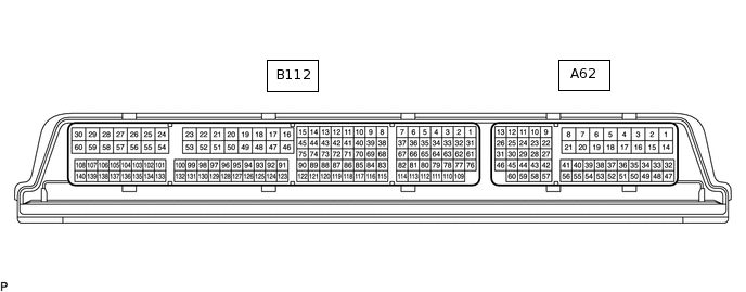
The standard voltage between each pair of the ECM terminals is shown in the table below. The appropriate conditions for checking each pair of the terminals are also indicated.
The result of checks should be compared with the standard voltage for that pair of terminals, which is displayed in the "Specified Condition" column.
The illustration above can be used as a reference to identify the ECM terminal locations.
Terminal No. (Symbol) |
Wiring Color |
Terminal Description |
Condition |
Specified Condition |
|---|---|---|---|---|
A62-1 (+B3) - A62-17 (E3) |
B - W-B |
Power source of ECM |
Ignition switch ON |
11 to 14 V |
A62-2 (+B) - A62-17 (E3) |
B - W-B |
Power source of ECM |
Ignition switch ON |
11 to 14 V |
A62-4 (E1) - Body ground |
W-B - - |
Ground |
Always |
Below 1 Ω |
A62-5 (E2) - Body ground |
W-B - - |
Ground |
Always |
Below 1 Ω |
A62-7 (D) - A62-4 (E1) |
L - W-B |
No. 2 clutch start switch assembly |
Ignition switch ON, clutch pedal released |
11 to 14 V |
Ignition switch ON, clutch pedal depressed |
0 to 1.5 V |
|||
A62-9 (MREL) - A62-17 (E3) |
B - W-B |
EFI MAIN NO. 1 relay |
Ignition switch ON |
11 to 14 V |
45 seconds elapsed since ignition switch off |
0 to 1.5 V |
|||
A62-10 (ST1-) - A62-4 (E1) |
GR - W-B |
Stop light switch assembly (opposite to STP) |
Ignition switch ON, brake pedal depressed |
0 to 1.5 V |
Ignition switch ON, brake pedal released |
7.5 to 14 V |
|||
A62-11 (R) - A62-4 (E1) |
R - W-B |
Back-up light switch signal |
Back-up light switch ON |
11 to 14 V |
A62-12 (CANN) - A62-4 (E1) |
W - W-B |
CAN communication line |
Ignition switch ON |
Pulse generation (See waveform 1) |
A62-13 (CANP) - A62-4 (E1) |
B - W-B |
CAN communication line |
Ignition switch ON |
Pulse generation (See waveform 2) |
A62-14 (+B2) - A62-17 (E3) |
B - W-B |
Power source of ECM |
Ignition switch ON |
11 to 14 V |
A62-15 (BATT) - A62-17 (E3) |
W - W-B |
Battery (for measuring the battery voltage and for the ECM memory) |
Always |
11 to 14 V |
A62-17 (E3) - Body ground |
W-B - - |
Ground |
Always |
Below 1 Ω |
A62-18 (E4) - Body ground |
W-B - - |
Ground |
Always |
Below 1 Ω |
A62-20 (FANL) - A62-4 (E1) |
R - W-B |
Cooling fan (low speed) |
Ignition switch ON |
11 to 14 V |
Idling with A/C on or high engine coolant temperature |
Below 1.5 V |
|||
A62-21 (TACH) - A62-4 (E1) |
GR - W-B |
Engine speed |
Idling |
Pulse generation (See waveform 3) |
A62-25 (CANL) - A62-4 (E1) |
W - W-B |
CAN communication line |
Ignition switch ON |
Pulse generation (See waveform 4) |
A62-26 (CANH) - A62-4 (E1) |
Y - W-B |
CAN communication line |
Ignition switch ON |
Pulse generation (See waveform 5) |
A62-27 (VCPA) - A62-22 (EPA) |
B - W |
Power source of accelerator pedal sensor assembly (for VPA) |
Ignition switch ON |
4.5 to 5.5 V |
A62-29 (VCP2) - A62-23 (EPA2) |
L - G |
Power source of accelerator pedal sensor assembly (for VPA2) |
Ignition switch ON |
4.5 to 5.5 V |
A62-30 (ELS2) - A62-4 (E1) |
P - W-B |
Electric load |
Defogger switch ON |
7.5 to 14 V |
Defogger switch off |
0 to 1.5 V |
|||
A62-32 (MHSW)* - A62-4 (E1) |
V - W-B |
Power heater switch signal |
Power heater switch ON |
11 to 14 V |
A62-36 (STA) - A62-4 (E1) |
SB - W-B |
Starter signal |
Cranking |
6.0 V or higher |
A62-37 (IGSW) - A62-17 (E3) |
B - W-B |
Ignition switch signal |
Ignition switch ON |
11 to 14 V |
A62-43 (VPA2) - A62-23 (EPA2) |
P - G |
Accelerator pedal sensor assembly (for sensor malfunction detection) |
Ignition switch ON, accelerator pedal fully released |
1.2 to 2.0 V |
Ignition switch ON, accelerator pedal fully depressed |
3.4 to 4.75 V |
|||
A62-45 (FANH) - A62-4 (E1) |
W - W-B |
Cooling fan (high speed) |
Idling with high engine coolant temperature |
Below 1.5 V |
A62-48 (STP) - A62-4 (E1) |
L - W-B |
Stop light switch assembly |
Ignition switch ON, brake pedal depressed |
7.5 to 14 V |
Ignition switch ON, brake pedal released |
0 to 1.5 V |
|||
A62-50 (TC) - A62-4 (E1) |
G - W-B |
Terminal TC of DLC3 |
Ignition switch ON |
11 to 14 V |
A62-51 (SPD) - A62-4 (E1) |
V - W-B |
Speed signal from combination meter |
Ignition switch ON, drive wheels rotating slowly |
Pulse generation (See waveform 6) |
A62-52 (VPA) - A62-22 (EPA) |
Y - W |
Accelerator pedal sensor assembly (for engine control) |
Ignition switch ON, accelerator pedal fully released |
0.5 to 1.1 V |
Ignition switch ON, accelerator pedal fully depressed |
2.6 to 4.5 V |
|||
A62-59 (W) - A62-4 (E1) |
R - W-B |
MIL |
MIL illuminated |
Below 3 V |
MIL not illuminated |
11 to 14 V |
|||
A62-60 (FC) - A62-4 (E1) |
W - W-B |
FUEL PUMP relay |
Ignition switch ON |
11 to 14 V |
Idling |
Below 1.5 V |
|||
B112-16 (ECBV) - A62-4 (E1) |
W-R - W-B |
EGR cooler bypass switching valve assembly |
Ignition switch ON with cold engine |
0 to 1.5 V |
Idling with warm engine |
11 to 14 V |
|||
B112-17 (HAF2) - A62-5 (E2) |
W-G - W-B |
Air fuel ratio sensor heater (for sensor 2) |
Ignition switch ON |
11 to 14 V |
Idling with warm engine |
Pulse generation (See waveform 7) |
|||
B112-21 (VN-A) - A62-4 (E1) |
W-B - W-B |
VN turbocharger motor |
Idling with warm engine |
Pulse generation (See waveform 8) |
B112-24 (VCPE) - A62-4 (E1) |
L - W-B |
Power source of exhaust gas pressure sensor |
Ignition switch ON |
4.5 to 5.5 V |
B112-26 (IJ4+) - B112-56 (IJ4-) |
R-G - BR-G |
No. 4 injector assembly |
Idling with warm engine |
Pulse generation (See waveform 9) |
B112-27 (IJ3+) - B112-57 (IJ3-) |
R-Y - BR-Y |
No. 3 injector assembly |
Idling with warm engine |
Pulse generation (See waveform 9) |
B112-28 (IJ2+) - B112-58 (IJ2-) |
R-L - BR-L |
No. 2 injector assembly |
Idling with warm engine |
Pulse generation (See waveform 9) |
B112-29 (IJ1+) - B112-59 (IJ1-) |
R-W - BR-W |
No. 1 injector assembly |
Idling with warm engine |
Pulse generation (See waveform 9) |
B112-30 (PCV) - A62-4 (E1) |
W-V - W-B |
Fuel quantity control valve |
Idling with warm engine |
Pulse generation (See waveform 10) |
B112-46 (HAF1) - A62-5 (E2) |
W-Y - W-B |
Air fuel ratio sensor heater (for sensor 1) |
Ignition switch ON |
11 to 14 V |
Idling with warm engine |
Pulse generation (See waveform 7) |
|||
B112-48 (EGM+) - B112-18 (EGM-) |
GR-R - W-Y |
EGR valve assembly (Motor) |
Idling with warm engine |
Pulse generation (See waveform 11) |
B112-49 (IA1+) - B112-19 (IA1-) |
W-GR - W-G |
Swirl control valve (Motor) |
Idling with warm engine |
Pulse generation (See waveform 12) |
B112-50 (M+) - B112-20 (M-) |
W-R - W-L |
Diesel throttle duty signal |
Idling with warm engine |
Pulse generation (See waveform 13) |
B112-51 (VN+A) - A62-4 (E1) |
W - W-B |
VN turbocharger motor |
Idling with warm engine |
Pulse generation (See waveform 14) |
B112-54 (VCS) - B112-102 (E2S) |
L-W - BR-GR |
Power source of fuel pressure sensor |
Ignition switch ON |
4.5 to 5.5 V |
B112-60 (PRV) - A62-5 (E2) |
W-B - W-B |
Pressure discharge valve |
Ignition switch ON |
Pulse generation (See waveform 15) |
B112-61 (VPIM) - B112-76 (EPIM) |
L-G - BR-L |
Power source of turbo pressure sensor assembly |
Ignition switch ON |
4.75 to 5.25 V |
B112-65 (VNVC) - B112-112 (VNE2) |
L-B - BR-O |
Power source of nozzle vane position sensor |
Ignition switch ON |
4.5 to 5.5 V |
B112-68 (G+) - B112-115 (G-) |
Y-V - BR-Y |
Camshaft position sensor |
Idling with warm engine |
Pulse generation (See waveform 16) |
B112-69 (VCEG) - B112-84 (EEGL) |
L - BR-G |
Power source of EGR valve position sensor |
Ignition switch ON |
4.5 to 5.5 V |
B112-70 (VCPX) - B112-71 (EPEX) |
L-GR - BR-O |
Power source of differential pressure sensor |
Ignition switch ON |
4.5 to 5.5 V |
B112-72 (VAC1) - A62-5 (E2) |
L-Y - W-B |
Power source of swirl control valve |
Ignition switch ON |
4.5 to 5.5 V |
B112-74 (LIN) - B112-96 (EGCU) |
V-W - BR-W |
LIN communication |
Ignition switch ON |
Pulse generation (See waveform 17) |
B112-79 (THIA) - B112-89 (ETHI) |
B-W - BR-W |
Intake air temperature sensor |
Idling, intake air temperature at 0 to 80°C (32 to 176°F) |
0.5 to 2.0 V |
B112-80 (VTAI) - B112-112 (VNE2) |
GR-W - BR-O |
Nozzle vane position sensor |
VN turbocharger fully closed |
0.9 to 2.1 V |
VN turbocharger fully opened |
3.0 to 4.1 V |
|||
B112-82 (THW) - B112-113 (ETHW) |
B-V - BR-B |
Engine coolant temperature sensor |
Idling, engine coolant temperature 60 to 120°C (140 to 248°F) |
0.2 to 1.0 V |
B112-83 (VCTA) - B112-81 (ETA) |
L-W - BR-O |
Power source of diesel throttle position sensor |
Ignition switch ON |
4.5 to 5.5 V |
B112-85 (PEX) - B112-71 (EPEX) |
B - BR-O |
Differential pressure sensor |
Ignition switch ON |
0.7 to 1.3 V |
Idling with warm engine |
0.5 to 4.5 V |
|||
B112-87 (IAC1) - B112-119 (EAC1) |
Y - BR-B |
Swirl control valve (Position sensor) |
Idling with warm engine |
0.5 to 4.5 V |
B112-92 (THCI) - B112-91 (ETCI) |
Y-L - BR-Y |
Exhaust gas temperature sensor (for sensor 1) |
Idling with warm engine |
2.9 to 3.3 V |
B112-93 (THF) - B112-124 (ETHF) |
L-G - BR-G |
Fuel temperature sensor |
Ignition switch ON |
0.5 to 2.0 V |
B112-97 (VG) - B112-129 (EVG) |
Y-B - BR-B |
Mass air flow meter signal |
Ignition switch ON |
Pulse generation (See waveform 18) |
B112-101 (PC) - B112-102 (E2S) |
Y-GR - BR-GR |
Fuel pressure sensor |
Idling |
1.0 to 1.3 V |
B112-103 (PEXM) - B112-135 (EPEM) |
Y - BR-O |
Exhaust gas pressure sensor |
Ignition switch ON (same as atmosphere pressure) |
0.7 to 1.3 V |
B112-109 (THCO) - B112-110 (ETCO) |
GR-W - BR |
Exhaust gas temperature sensor (for sensor 2) |
Idling with warm engine |
2.9 to 3.3 V |
B112-111 (PIM) - B112-76 (EPIM) |
B-L - BR-L |
Turbo pressure sensor assembly |
Ignition switch ON (same as atmosphere pressure) |
0.8 to 1.4 V |
B112-114 (THA) - B112-129 (EVG) |
GR-B - BR-B |
Intake air temperature sensor (built into mass air flow meter sub-assembly) |
Idling, intake air temperature 20°C (68°F) |
0.5 to 2.0 V |
B112-116 (EGLS) - B112-84 (EEGL) |
B - BR-G |
EGR valve assembly (Position sensor) |
Idling with warm engine |
0.5 to 4.5 V |
B112-118 (THEC) - B112-86 (ETEC) |
Y-L - BR-Y |
EGR gas temperature sensor |
Idling with warm engine |
0 to 5 V |
B112-117 (VTA1) - B112-81 (ETA) |
GR-W - BR-O |
Diesel throttle position sensor |
Throttle valve fully opened |
3.2 to 4.9 V |
Throttle valve fully closed |
0.5 to 1.1 V |
|||
B112-121 (NE+) - B112-90 (NE-) |
B-R - BR-R |
Crankshaft position sensor |
Idling with warm engine |
Pulse generation (See waveform 19) |
B112-122 (VCNE) - B112-90 (NE-) |
L-R - BR-R |
Power source of crankshaft position sensor |
Ignition switch ON |
4.5 to 5.5 V |
B112-125 (RE1) - A62-5 (E2) |
B-Y - W-B |
Air fuel ratio sensor signal (for sensor 1) |
Idling with warm engine |
2.1 to 3.5 V |
B112-126 (AF1-) - A62-5 (E2) |
BR - W-B |
Air fuel ratio sensor signal (for sensor 1) |
Idling with warm engine |
2.35 to 2.65 V |
B112-127 (AF1+) - A62-5 (E2) |
GR-BR - W-B |
Air fuel ratio sensor signal (for sensor 1) |
Idling with warm engine |
1.5 to 4.9 V |
B112-128 (TR1) - A62-5 (E2) |
GR-L - W-B |
Air fuel ratio sensor signal (for sensor 1) |
Idling with warm engine |
1.5 to 4.9 V |
B112-131 (TR2) - A62-5 (E2) |
GR-W - W-B |
Air fuel ratio sensor signal (for sensor 2) |
Idling with warm engine |
1.5 to 4.9 V |
B112-130 (AF2+) - A62-5 (E2) |
GR - W-B |
Air fuel ratio sensor signal (for sensor 2) |
Idling with warm engine |
1.5 to 4.9 V |
B112-133 (AF2-) - A62-5 (E2) |
BR-R - W-B |
Air fuel ratio sensor signal (for sensor 2) |
Idling with warm engine |
2.35 to 2.65 V |
B112-134 (RE2) - A62-5 (E2) |
B-W - W-B |
Air fuel ratio sensor signal (for sensor 2) |
Idling with warm engine |
2.1 to 3.5 V |
*: w/ Power Heater (Combination Type)
WAVEFORM 1
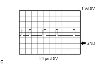
Table 1. CAN communication signal Item
Content
ECM Terminal Name
Between CANN and E1
Tester Range
1 V/DIV., 20 μs./DIV.
Condition
Ignition switch ON
WAVEFORM 2
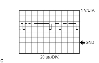
Table 2. CAN communication signal Item
Content
ECM Terminal Name
Between CANP and E1
Tester Range
1 V/DIV., 20 μs./DIV.
Condition
Ignition switch ON
WAVEFORM 3
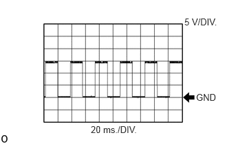
Table 3. Engine speed signal Item
Content
ECM Terminal Name
Between TACH and E1
Tester Range
5 V/DIV., 20 ms./DIV.
Condition
Idling
WAVEFORM 4
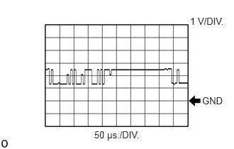
Table 4. CAN communication signal Item
Content
ECM Terminal Name
Between CANL and E1
Tester Range
1 V/DIV., 50 μs./DIV.
Condition
Ignition switch ON
WAVEFORM 5
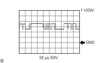
Table 5. CAN communication signal Item
Content
ECM Terminal Name
Between CANH and E1
Tester Range
1 V/DIV., 50 μs./DIV.
Condition
Ignition switch ON
WAVEFORM 6
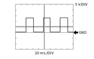
Table 6. Vehicle speed signal Item
Content
ECM Terminal Name
Between SPD and E1
Tester Range
5 V/DIV., 20 ms./DIV.
Condition
Ignition switch ON, drive wheels rotating slowly
Tip:The wavelength becomes shorter as the vehicle speed increases.
WAVEFORM 7
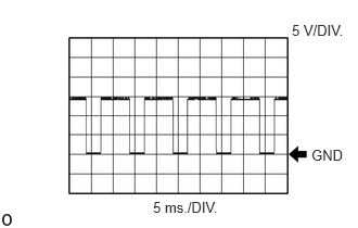
Table 7. Air fuel ratio sensor heater signal Item
Content
ECM Terminal Name
Between HAF1 and E2
Between HAF2 and E2
Tester Range
5 V/DIV., 5 ms./DIV.
Condition
Idling with warm engine
WAVEFORM 8
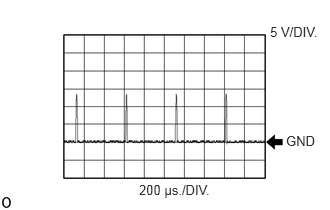
Table 8. VN turbocharger motor signal Item
Content
ECM Terminal Name
Between VN-A and E1
Tester Range
5 V/DIV., 200 μs./DIV.
Condition
Idling with warm engine
WAVEFORM 9
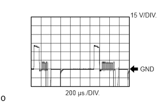
Table 9. Injector signal Item
Content
ECM Terminal Name
Between IJ1+ and IJ1-
Between IJ2+ and IJ2-
Between IJ3+ and IJ3-
Between IJ4+ and IJ4-
Tester Range
15 V/DIV., 200 μs./DIV.
Condition
Idling with warm engine
WAVEFORM 10

Table 10. Fuel quantity control valve signal Item
Content
ECM Terminal Name
Between PCV and E1
Tester Range
5 V/DIV., 2 ms./DIV.
Condition
Idling with warm engine
WAVEFORM 11

Table 11. EGR valve motor signal Item
Content
ECM Terminal Name
Between EGM+ and EGM-
Tester Range
5 V/DIV., 200 μs./DIV.
Condition
Idling with warm engine
WAVEFORM 12
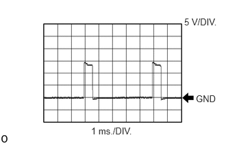
Table 12. Swirl control valve motor signal Item
Content
ECM Terminal Name
Between IA1+ and IA1-
Tester Range
5 V/DIV., 1 ms./DIV.
Condition
Idling with warm engine
WAVEFORM 13
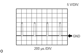
Table 13. Diesel throttle duty signal Item
Content
ECM Terminal Name
Between M+ and M-
Tester Range
5 V/DIV., 200 μs./DIV.
Condition
Idling with warm engine
WAVEFORM 14
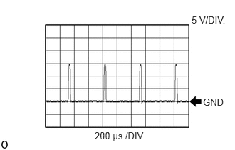
Table 14. VN turbocharger motor signal Item
Content
ECM Terminal Name
Between VN+A and E1
Tester Range
5 V/DIV., 200 μs./DIV.
Condition
Idling with warm engine
WAVEFORM 15
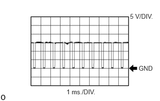
Table 15. Pressure discharge valve signal Item
Content
ECM Terminal Name
Between PRV and E2
Tester Range
5 V/DIV., 1 ms./DIV.
Condition
Ignition switch ON
WAVEFORM 16
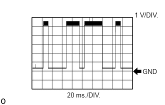
Table 16. Camshaft position sensor signal Item
Content
ECM Terminal Name
Between G+ and G-
Tester Range
1 V/DIV., 20 ms./DIV.
Condition
Idling with warm engine
WAVEFORM 17
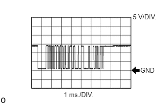
Table 17. LIN communication signal Item
Content
ECM Terminal Name
Between LIN and EGCU
Tester Range
5 V/DIV., 1 ms./DIV.
Condition
Ignition switch ON
WAVEFORM 18
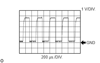
Table 18. Mass air flow meter signal Item
Content
ECM Terminal Name
Between VG and EVG
Tester Range
1 V/DIV., 200 μs./DIV.
Condition
Ignition switch ON
WAVEFORM 19
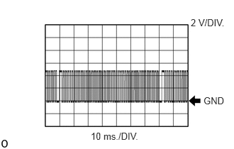
Table 19. Crankshaft position sensor signal Item
Content
ECM Terminal Name
Between NE+ and NE-
Tester Range
2 V/DIV., 10 ms./DIV.
Condition
Idling with warm engine