ECD SYSTEM(w/ Glow Plug Controller), Diagnostic DTC:P064C,P066B,P066D,P066F,P0671,P0672,P0673,P0674,P067B and P166F
| DTC Code | DTC Name |
|---|---|
| P064C | Glow Plug Control Module |
| P066B | Cylinder 1 Glow Plug Control Circuit High |
| P066D | Cylinder 2 Glow Plug Control Circuit High |
| P066F | Cylinder 3 Glow Plug Control Circuit High |
| P0671 | Cylinder 1 Glow Plug Circuit/Open |
| P0672 | Cylinder 2 Glow Plug Circuit/Open |
| P0673 | Cylinder 3 Glow Plug Circuit/Open |
| P0674 | Cylinder 4 Glow Plug Circuit/Open |
| P067B | Cylinder 4 Glow Plug Control Circuit High |
| P166F | Glow Plug Control Module Circuit Short |
DESCRIPTION
Refer to DTC P052F.
DTC No. |
Detection Item |
DTC Detection Condition |
Trouble Area |
MIL |
Memory |
|---|---|---|---|---|---|
P064C |
Glow Plug Control Module |
The MOS inside the glow plug controller is detected as being stuck on 3 times while the glow plug assemblies are on (2 trip detection logic). |
Glow plug controller |
Comes on |
DTC stored |
P066B |
Cylinder 1 Glow Plug Control Circuit High |
A short circuit in the No. 1 glow plug circuit is detected 3 times while the glow plug assemblies are on (2 trip detection logic). |
|
Comes on |
DTC stored |
P066D |
Cylinder 2 Glow Plug Control Circuit High |
A short circuit in the No. 2 glow plug circuit is detected 3 times while the glow plug assemblies are on (2 trip detection logic). |
|
Comes on |
DTC stored |
P066F |
Cylinder 3 Glow Plug Control Circuit High |
A short circuit in the No. 3 glow plug circuit is detected 3 times while the glow plug assemblies are on (2 trip detection logic). |
|
Comes on |
DTC stored |
P0671 |
Cylinder 1 Glow Plug Circuit/Open |
An open circuit in the No. 1 glow plug circuit is detected 3 times while the glow plug assemblies are on (2 trip detection logic). |
|
Comes on |
DTC stored |
P0672 |
Cylinder 2 Glow Plug Circuit/Open |
An open circuit in the No. 2 glow plug circuit is detected 3 times while the glow plug assemblies are on (2 trip detection logic). |
|
Comes on |
DTC stored |
P0673 |
Cylinder 3 Glow Plug Circuit/Open |
An open circuit in the No. 3 glow plug circuit is detected 3 times while the glow plug assemblies are on (2 trip detection logic). |
|
Comes on |
DTC stored |
P0674 |
Cylinder 4 Glow Plug Circuit/Open |
An open circuit in the No. 4 glow plug circuit is detected 3 times while the glow plug assemblies are on (2 trip detection logic). |
|
Comes on |
DTC stored |
P067B |
Cylinder 4 Glow Plug Control Circuit High |
A short circuit in the No. 4 glow plug circuit is detected 3 times while the glow plug assemblies are on (2 trip detection logic). |
|
Comes on |
DTC stored |
P166F |
Glow Plug Control Module Circuit Short |
A short circuit in a wire harness between the glow plugs is detected 3 times while the glow plug assemblies are on (2 trip detection logic). |
|
Comes on |
DTC stored |
DTC No. |
DTC Detection Drive Pattern |
|---|---|
P064C |
Ignition switch ON (Engine coolant temperature is 40°C (104°F) or less) |
P066B |
Ignition switch ON (Engine coolant temperature is 40°C (104°F) or less) |
P066D |
|
P066F |
|
P0671 |
|
P0672 |
|
P0673 |
|
P0674 |
|
P067B |
|
P166F |
WIRING DIAGRAM
Refer to DTC P052F.
CAUTION / NOTICE / HINT
When replacing the ECM, perform ECM Initialization and Registration.
Inspect the fuses of circuits related to this system before performing the following procedure.
After turning ignition switch off, waiting time may be required before disconnecting the cable from the negative (-) battery terminal. Therefore, make sure to read the disconnecting the cable from the negative (-) battery terminal notices before proceeding with work.
When the ECM must be replaced, before replacing the ECM, perform the "Learning Values Save" function using the GTS. Then after installing a new ECM, perform all of the initialization and registration procedures for the "Learning Values Write" function by following the instructions shown on the GTS display.
Read freeze frame data using the GTS. Freeze frame data records the engine condition when malfunctions are detected. When troubleshooting, freeze frame data can help determine if the vehicle was moving or stationary, if the engine was warmed up or not, and other data from the time the malfunction occurred.
PROCEDURE
CHECK DTC OUTPUT
Connect the GTS to the DLC3.
Turn the ignition switch to ON and turn the GTS on.
Enter the following menus: Powertrain / Engine and ECT / Trouble Codes.
Read the DTCs.
Powertrain > Engine and ECT > Trouble Codes
Result
Result
Proceed to
DTC P0671, P0672, P0673 and/or P0674 is output
A
DTC P066B, P066D, P066F and/or P067B is output
B
DTC P064C and/or P166F is output
C
B CHECK HARNESS AND CONNECTOR (GLOW PLUG CONTROLLER - NO. 1 GLOW PLUG CONNECTOR)Click here
C CHECK HARNESS AND CONNECTOR (GLOW PLUG CONTROLLER - NO. 1 GLOW PLUG CONNECTOR)Click here
CHECK TERMINAL VOLTAGE (POWER SOURCE OF GLOW PLUG CONTROLLER)
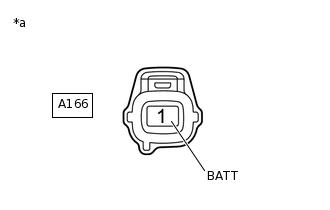
*a
Front view of wire harness connector
(to Glow Plug Controller)
Disconnect the glow plug controller connector.
Turn the ignition switch to ON.
Measure the voltage according to the value(s) in the table below.
Standard Voltage
Tester Connection
Condition
Specified Condition
A166-1 (BATT) - Body ground
Ignition switch ON
11 to 14 V
Result
Proceed to
OK
NG
NG INSPECT GLOW PLUG RELAY ASSEMBLYClick here
CHECK HARNESS AND CONNECTOR (GLOW PLUG CONTROLLER - NO. 1 GLOW PLUG CONNECTOR)
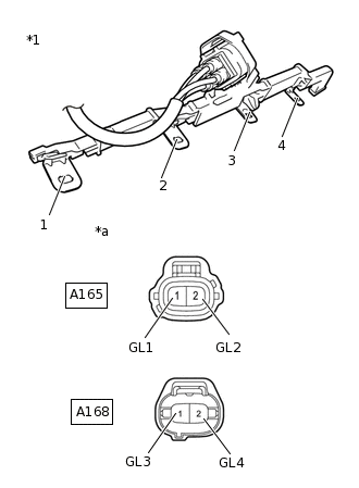
*1
No. 1 Glow Plug Connector
*a
Front view of wire harness connector
(to Glow Plug Controller)
Disconnect connectors of the glow plug controller.
Remove the No. 1 glow plug connector from the glow plug.
Measure the resistance according to the value(s) in the table below.
Standard Resistance
Tester Connection
Condition
Specified Condition
A165-1 (GL1) - 1 (No. 1 glow plug connector terminal)
Always
Below 1 Ω
A165-2 (GL2) - 2 (No. 1 glow plug connector terminal)
Always
Below 1 Ω
A168-1 (GL3) - 3 (No. 1 glow plug connector terminal)
Always
Below 1 Ω
A168-2 (GL4) - 4 (No. 1 glow plug connector terminal)
Always
Below 1 Ω
Result
Proceed to
OK
NG
NG REPAIR OR REPLACE HARNESS OR CONNECTORClick here
INSPECT GLOW PLUG ASSEMBLY
Connect the GTS to the DLC3.
Turn the ignition switch to ON and GTS on.
Clear the DTCs.
Powertrain > Engine and ECT > Clear DTCs
Turn the ignition switch off.
Exchange the glow plug assemblies of the malfunctioning cylinders (the cylinders indicated by output DTCs) with the glow plugs of normally functioning cylinders.
Turn the ignition switch to ON when the engine temperature is 40°C (104°F) or less.
Turn the GTS on.
Enter the following menus: Powertrain / Engine and ECT / Trouble Codes / Pending.
Read the pending DTCs.
Powertrain > Engine and ECT > Trouble Codes
Result
Result
Proceed to
Same DTCs (that have been erased)
A
Other DTCs
B
A REPLACE GLOW PLUG CONTROLLERClick here
REPLACE GLOW PLUG ASSEMBLY
Replace the glow plug assembly.
Result
Proceed to
NEXT
NEXT CONFIRM WHETHER MALFUNCTION HAS BEEN SUCCESSFULLY REPAIREDClick here
REPAIR OR REPLACE HARNESS OR CONNECTOR
Repair or replace the harness or connector.
Result
Proceed to
NEXT
CONFIRM WHETHER MALFUNCTION HAS BEEN SUCCESSFULLY REPAIRED
Connect the GTS to the DLC3.
Turn the ignition switch to ON.
Turn the GTS on.
Clear the DTCs.
Powertrain > Engine and ECT > Clear DTCs
Turn the ignition switch off for 30 seconds or more.
Turn the ignition switch to ON when the engine coolant temperature is 40°C (104°F) or less.
Turn the GTS on.
Enter the following menus: Powertrain / Engine and ECT / Trouble Codes / Pending.
Confirm that the pending DTC is not output.
Powertrain > Engine and ECT > Trouble Codes
Result
Proceed to
NEXT
NEXT END
INSPECT GLOW PLUG RELAY ASSEMBLY
Inspect the glow plug relay assembly.
Result
Proceed to
OK
NG
NG REPLACE GLOW PLUG RELAY ASSEMBLYClick here
CHECK HARNESS AND CONNECTOR (BATTERY - GLOW PLUG RELAY ASSEMBLY - ECM)
Disconnect the cable from the negative (-) battery terminal.
Disconnect the cable from the positive (+) battery terminal.
Remove the glow plug relay assembly.
Disconnect of the glow plug controller connectors.
Disconnect the ECM connectors.
Measure the resistance according to the value(s) in the table below.
Standard Resistance
Tester Connection
Condition
Specified Condition
A100-4 - Battery positive terminal
Always
Below 1 Ω
A100-1 - 3 (EFI-MAIN relay)
Always
Below 1 Ω
A100-3 - A166-1 (BATT)
Always
Below 1 Ω
A100-2 - A169-20 (GREL)
Always
Below 1 Ω
A100-4 or Battery positive terminal - Body ground
Always
10 kΩ or higher
A100-1 or 3 (EFI-MAIN relay) - Body ground and other terminals
Always
10 kΩ or higher
A100-3 or A166-1 (BATT) - Body ground and other terminals
Always
10 kΩ or higher
A100-2 or A169-20 (GREL) - Body ground and other terminals
Always
10 kΩ or higher
Result
Proceed to
OK
NG
NG REPAIR OR REPLACE HARNESS OR CONNECTORClick here
CHECK TERMINAL VOLTAGE (POWER SOURCE OF GLOW PLUG RELAY ASSEMBLY)
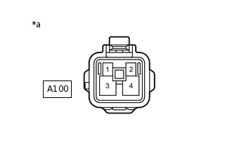
*a
Front view of wire harness connector
(to Glow Plug Relay Assembly)
Remove the glow plug relay assembly.
Turn the ignition switch to ON.
Measure the voltage according to the value(s) in the table below.
Standard Voltage
Tester Connection
Condition
Specified Condition
A100-1 - Body ground
Ignition switch ON
11 to 14 V
Result
Proceed to
OK
NG
NG REPAIR OR REPLACE HARNESS OR CONNECTORClick here
REPLACE ECM
Replace the ECM.
Result
Proceed to
NEXT
NEXT CONFIRM WHETHER MALFUNCTION HAS BEEN SUCCESSFULLY REPAIREDClick here
REPAIR OR REPLACE HARNESS OR CONNECTOR
Result
Proceed to
NEXT
NEXT CONFIRM WHETHER MALFUNCTION HAS BEEN SUCCESSFULLY REPAIREDClick here
REPLACE GLOW PLUG RELAY ASSEMBLY
Replace the glow plug relay assembly.
Result
Proceed to
NEXT
CONFIRM WHETHER MALFUNCTION HAS BEEN SUCCESSFULLY REPAIRED
Connect the GTS to the DLC3.
Turn the ignition switch to ON.
Turn the GTS on.
Clear the DTCs.
Powertrain > Engine and ECT > Clear DTCs
Turn the ignition switch off for 30 seconds or more.
Turn the ignition switch to ON when the engine temperature is 40°C (104°F) or less.
Turn the GTS on.
Enter the following menus: Powertrain / Engine and ECT / Trouble Codes / Pending.
Confirm that the pending DTC is not output.
Powertrain > Engine and ECT > Trouble Codes
Result
Proceed to
NEXT
NEXT END
CHECK HARNESS AND CONNECTOR (GLOW PLUG CONTROLLER - NO. 1 GLOW PLUG CONNECTOR)
*1
No. 1 Glow Plug Connector
*a
Front view of wire harness connector
(to Glow Plug Controller)
Disconnect connectors of the glow plug controller.
Remove the No. 1 glow plug connector from the glow plug.
Measure the resistance according to the value(s) in the table below.
Standard Resistance
Tester Connection
Condition
Specified Condition
A165-1 (GL1) - 1 (No. 1 glow plug connector terminal)
Always
Below 1 Ω
A165-2 (GL2) - 2 (No. 1 glow plug connector terminal)
Always
Below 1 Ω
A168-1 (GL3) - 3 (No. 1 glow plug connector terminal)
Always
Below 1 Ω
A168-2 (GL4) - 4 (No. 1 glow plug connector terminal)
Always
Below 1 Ω
Result
Proceed to
OK
NG
NG REPAIR OR REPLACE HARNESS OR CONNECTORClick here
REPLACE GLOW PLUG CONTROLLER
Replace the glow plug controller.
Result
Proceed to
NEXT
NEXT CONFIRM WHETHER MALFUNCTION HAS BEEN SUCCESSFULLY REPAIREDClick here
REPAIR OR REPLACE HARNESS OR CONNECTOR
Repair or replace the harness or connector.
Result
Proceed to
NEXT
CONFIRM WHETHER MALFUNCTION HAS BEEN SUCCESSFULLY REPAIRED
Connect the GTS to the DLC3.
Turn the ignition switch to ON.
Turn the GTS on.
Clear the DTCs.
Powertrain > Engine and ECT > Clear DTCs
Turn the ignition switch off for 30 seconds or more.
Turn the ignition switch to ON when the engine temperature is 40°C (104°F) or less.
Turn the GTS on.
Enter the following menus: Powertrain / Engine and ECT / Trouble Codes / Pending.
Confirm that the pending DTC is not output.
Powertrain > Engine and ECT > Trouble Codes
Result
Result
Proceed to
DTC is not output
A
DTC P066B, P066D, P066F and/or P067B is output
B
A END
REPLACE GLOW PLUG ASSEMBLY
Replace the glow plug assembly.
Result
Proceed to
NEXT
NEXT CONFIRM WHETHER MALFUNCTION HAS BEEN SUCCESSFULLY REPAIREDClick here
CHECK HARNESS AND CONNECTOR (GLOW PLUG CONTROLLER - NO. 1 GLOW PLUG CONNECTOR)
*1
No. 1 Glow Plug Connector
*a
Front view of wire harness connector
(to Glow Plug Controller)
Disconnect connectors of the glow plug controller.
Remove the No. 1 glow plug connector from the glow plug.
Measure the resistance according to the value(s) in the table below.
Standard Resistance
Tester Connection
Condition
Specified Condition
A165-1 (GL1) - 1 (No. 1 glow plug connector terminal)
Always
Below 1 Ω
A165-2 (GL2) - 2 (No. 1 glow plug connector terminal)
Always
Below 1 Ω
A168-1 (GL3) - 3 (No. 1 glow plug connector terminal)
Always
Below 1 Ω
A168-2 (GL4) - 4 (No. 1 glow plug connector terminal)
Always
Below 1 Ω
Result
Proceed to
OK
NG
NG REPAIR OR REPLACE HARNESS OR CONNECTORClick here
REPLACE GLOW PLUG CONTROLLER
Replace the glow plug controller.
Result
Proceed to
NEXT
NEXT CONFIRM WHETHER MALFUNCTION HAS BEEN SUCCESSFULLY REPAIREDClick here
REPAIR OR REPLACE HARNESS OR CONNECTOR
Result
Proceed to
NEXT
CONFIRM WHETHER MALFUNCTION HAS BEEN SUCCESSFULLY REPAIRED
Connect the GTS to the DLC3.
Turn the ignition switch to ON.
Turn the GTS on.
Clear the DTCs.
Powertrain > Engine and ECT > Clear DTCs
Turn the ignition switch off for 30 seconds or more.
Turn the ignition switch to ON when the engine temperature is 40°C (104°F) or less.
Turn the GTS on.
Enter the following menus: Powertrain / Engine and ECT / Trouble Codes / Pending.
Confirm that the pending DTC is not output.
Powertrain > Engine and ECT > Trouble Codes
Result
Proceed to
NEXT
NEXT END