REAR AXLE SHAFT INSTALLATION

-
INSTALL REAR AXLE SHAFT OIL SEAL (w/ ABS)
-
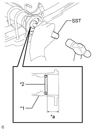
Text in Illustration *1 Rear Axle Housing Assembly *2 Rear Axle Shaft Oil Seal *a Seal installation depth Using SST and a hammer, install a new rear axle shaft oil seal.
- SST
- 09554-22010
Seal installation depth 34.5 to 35.5 mm (1.358 to 1.398 in.) Note
-
Do not drive the oil seal in deeper than the specified range or an oil leak will occur.
-
Do not tilt the oil seal during installation.
-
Apply MP grease to the oil seal lip.
-
-
INSTALL REAR AXLE SHAFT OIL SEAL (w/o ABS)
-
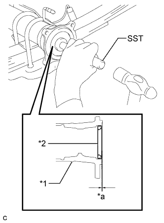
Text in Illustration *1 Rear Axle Housing Assembly *2 Rear Axle Shaft Oil Seal *a Seal installation depth Using SST and a hammer, install a new rear axle shaft oil seal.
- SST
- 09554-22010
Seal installation depth 0.5 to 1.5 mm (0.0197 to 0.0590 in.) Note
-
Do not drive the oil seal in deeper than the specified range or an oil leak will occur.
-
Do not tilt the oil seal during installation.
-
Apply MP grease to the oil seal lip.
-
-
INSTALL BEARING RETAINER O-RING
-
Apply MP grease to the bearing retainer O-ring.
-
Install the bearing retainer O-ring to the rear axle shaft housing.
-
-
INSTALL REAR AXLE SHAFT WITH BACKING PLATE
-
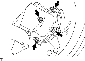
Install the rear axle shaft with backing plate to the rear axle shaft housing with the 4 nuts.
- Torque:
- 65 N*m { 663 kgf*cm, 48 ft.*lbf }
Note
-
Be careful not to damage the rear axle shaft oil seal.
-
Be careful not to damage the skid control rotor rear.
-
-
INSTALL REAR SPEED SENSOR (w/ ABS)
-
Install the rear speed sensor LH with the bolt.
- Torque:
- 8.5 N*m { 87 kgf*cm, 75 in.*lbf }
Note
Prevent foreign matter from attaching to the sensor tip.
-
Attach the 3 clips.
-
Connect the connector and attach the connector clamp.
-
-
INSTALL REAR WHEEL BRAKE CYLINDER ASSEMBLY
-
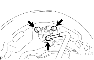
Install the wheel brake cylinder assembly with the 2 bolts.
- Torque:
- 9.5 N*m { 97 kgf*cm, 84 in.*lbf }
-
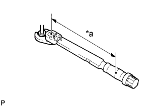
Text in Illustration *a Torque Wrench Fulcrum Length Using a union nut wrench, connect the brake tube.
- Torque:
- Specified tightening torque
- 15 N*m { 155 kgf*cm, 11 ft.*lbf }
Tech Tips
-
Calculate the torque wrench reading when changing the fulcrum length of the torque wrench Click here.
-
When using a union nut wrench (fulcrum length of 22 mm (0.8661 in.)) + torque wrench (fulcrum length of 162 mm (6.3779 in.)): 13 N*m (137 kgf*cm, 10 ft.*lbf)
-
-
APPLY HIGH TEMPERATURE GREASE
-
Text in Illustration *1 High temperature grease Apply high temperature grease to the shoe attached surface of the backing plate.
-
-
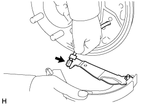
INSTALL PARKING BRAKE CABLE ASSEMBLY NO.3
-
Install the parking brake cable assembly No.3 to the rear brake backing plate with the 2 bolts.
- Torque:
- 8.0 N*m { 82 kgf*cm, 71 in.*lbf }
-
-
INSTALL PARKING BRAKE SHOE STRUT SET
-
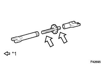
Text in Illustration *1 High temperature grease Apply the high temperature grease to the adjusting bolt.
-
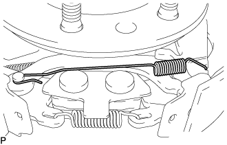
Install the tension spring to the shoe strut set.
-
-
INSTALL REAR BRAKE SHOE
-
for 254 mm drum:
-
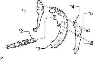
Text in Illustration *1 Brake Shoe Lever *2 Brake Shoe Strut Set *3 Rear Brake Shoe *4 Rear Cushion Lever *5 C-washer Using pliers, install the rear brake shoe, shoe strut set, rear cushion lever and shoe lever with a new C-washer.
-
Connect the parking brake cable No. 3 to the front brake shoe.
-
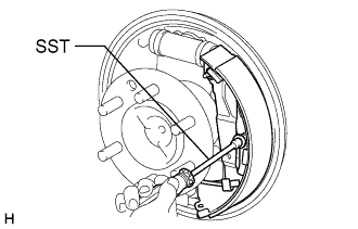
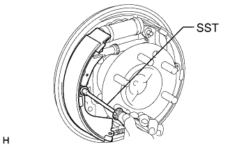
Using SST, install the rear brake shoe, pin, shoe hold down spring and shoe hold down cup.
- SST
- 09718-00011
-
-
for 295 mm drum:
-
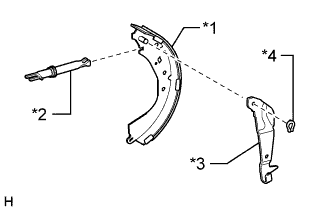
Text in Illustration *1 Rear Brake Shoe *2 Brake Shoe Strut Set *3 Brake Shoe Lever *4 C-washer Install the rear brake shoe, brake shoe strut set and shoe lever with a new C-washer.
-
Connect the parking brake cable No. 3 to the front brake shoe.
-
Using SST, install the rear brake shoe, pin, shoe hold down spring and shoe hold down cup.
- SST
- 09718-00011
-
-
-
INSTALL FRONT BRAKE SHOE
-
for 254 mm drum:
-
Install the return spring to each brake shoe.
-
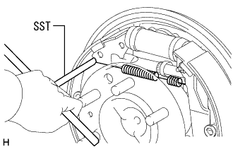
Using SST, install the front brake shoe, pin, shoe hold down spring and shoe hold down cup.
- SST
- 09718-00011
-
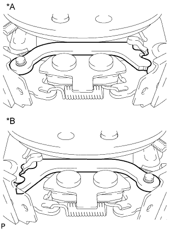
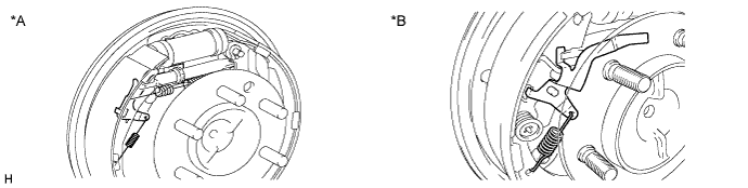
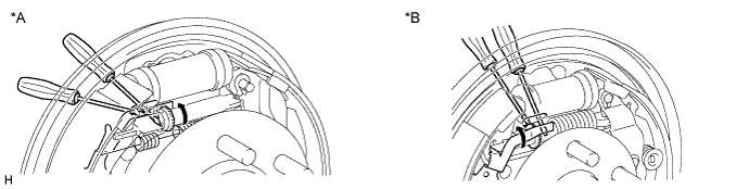
Text in Illustration *A LH Side *B RH Side Install the brake shoe lower strut.
Note
Make sure that the shoe lower strut and brake rear cushion lever are securely engaged.
-
Using needle-nose pliers, install the tension spring.
-
-
for 295 mm drum:
-
Using SST, install the front brake shoe, pin, shoe hold down spring and shoe hold down cup.
- SST
- 09718-00011
-
Install the return spring to each brake shoe.
-
-
-
CONNECT PARKING BRAKE SHOE STRUT SET
-
for 254 mm drum:
-
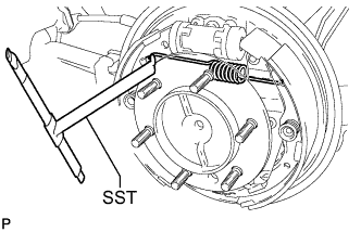
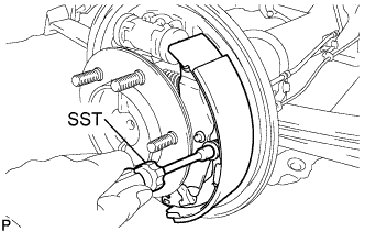
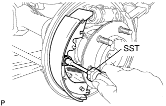
Using SST, install the upper side tension spring.
- SST
- 09703-30011
-
-
for 295 mm drum:
-
Using SST, install the upper side tension spring.
- SST
- 09703-30011
-
-
-
INSTALL AUTOMATIC ADJUST LEVER
-
Install the automatic adjust lever and tension spring.
Text in Illustration *A for 295 mm Drum *B for 254 mm Drum Note
Make sure to install the automatic adjust lever between the groove of the shoe strut set and brake shoe.
-
-
INSPECT REAR DRUM BRAKE
-
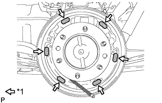
Check the each part is installed properly.
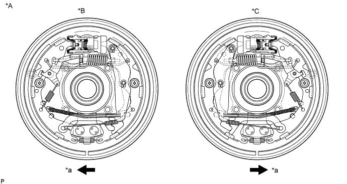
Text in Illustration *A for 254 mm Drum *B LH Side *C RH Side - - *a Front - - 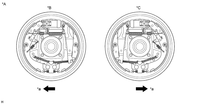
Text in Illustration *A for 295 mm Drum *B LH Side *C RH Side - - *a Front - - Note
There should be no oil or grease adhering to the friction surfaces of the shoe lining and drum.
-
If they are not installed correctly, reinstall them as shown in the illustration.
-
-
INSTALL REAR AXLE BRAKE DRUM GASKET
-
Install the new brake drum gasket to the rear axle shaft.
-
-
INSTALL REAR BRAKE DRUM SUB-ASSEMBLY
-
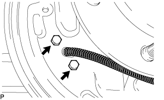
ADJUST REAR DRUM BRAKE SHOE CLEARANCE
-
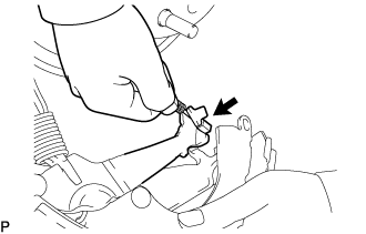
Using a screwdriver from a service hole, turn the adjuster to expand the shoes so that the brake shoes touch the brake drum.
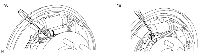
Text in Illustration *A for 295 mm Drum *B for 254 mm Drum -
Using another screwdriver, push up the automatic adjust lever and turn the adjuster to contract the shoes so that the brake shoe does not touch the brake drum. Then turn the adjuster another 180 degrees to further contract the shoes.
Text in Illustration *A for 295 mm Drum *B for 254 mm Drum -
Install the hole plug.
-
-
ADD BRAKE FLUID
-
w/ VSC: Click here
-
w/o VSC: Click here
-
-
BLEED BRAKE LINE
-
w/ VSC: Click here
-
w/o VSC: Click here
-
-
INSPECT BRAKE FLUID LEVEL
-
w/ VSC: Click here
-
w/o VSC: Click here
-
-
INSTALL REAR WHEEL
- Torque:
- 100 N*m { 1,020 kgf*cm, 74 ft.*lbf }
-
INSPECT PARKING BRAKE CONTROL HANDLE TRAVEL
-
Pull firmly on the parking brake control handle.
-
Release the parking brake lock, and return the parking brake control handle to its off position.
-
Slowly pull the parking brake control handle all the way up, and count the number of clicks.
Parking brake control handle travel 10 to 16 clicks at 200 N (20 kgf, 44 lbf) (except Super Long Wheelbase) 12 to 18 clicks at 200 N (20 kgf, 44 lbf) (for Super Long Wheelbase) Tech Tips
-
If the number of clicks falls outside of the specified range, release the parking brake lock and adjust it.
-
If there are fewer clicks than the specified value, loosen the parking brake wire adjustment nut an the lock nut. With the parking brake cable loosened, adjust the clearance between the brake drum and lining.
-
-
-
ADJUST PARKING BRAKE CONTROL HANDLE TRAVEL
-
Lift the vehicle
-
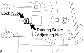
Depress the parking brake handle. Hold the parking brake adjusting nut using a wrench, and loosen the lock nut.
-
Turn the parking brake adjusting nut until the parking brake handle travel meets the above specification.
Parking brake control handle travel 10 to 16 clicks at 200 N (20 kgf, 44 lbf) (except Super Long Wheelbase) 12 to 18 clicks at 200 N (20 kgf, 44 lbf) (for Super Long Wheelbase) -
Count the number of clicks after depressing and releasing the parking brake control handle 3 or 4 times.
-
Check whether the parking brake drags or not.
-
When operating the parking brake control handle, check that the parking brake indicator light comes on.
Standard Brake warning light always comes on at the first click. -
Hold the parking brake adjusting nut using a wrench, and tighten the lock nut.
- Torque:
- 14.5 N*m { 148 kgf*cm, 11 ft.*lbf }
-
Lower the vehicle.
-
-
CHECK ABS SPEED SENSOR SIGNAL (w/ ABS)
-
w/ VSC: Click here
-
w/o VSC: Click here
-