FUEL PRESSURE REGULATOR REMOVAL
-
DISCHARGE FUEL SYSTEM PRESSURE
CAUTION:
-
Do not disconnect any part of the fuel system until you have discharged the fuel system pressure.
-
Even after discharging the fuel pressure, place a cloth or equivalent over fittings as you separate them to reduce risk of fuel spray on yourself or in the engine compartment.
-
Disconnect the cable from the negative (-) battery terminal.
CAUTION:
Wait at least 90 seconds after disconnecting the cable from the negative (-) battery terminal to prevent airbag and seat belt pretensioner activation.
-
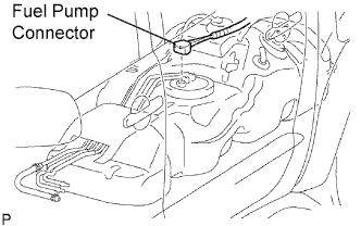
Disconnect the fuel pump connector.
-
Connect the cable to the negative (-) battery terminal.
-
Start the engine. After the engine has stopped on its own, turn the ignition switch OFF.
Tech Tips
DTC P0171/25 (system too lean) may be set.
-
Crank the engine again, then check that the engine does not start.
-
Loosen the fuel tank cap, then discharge the pressure in the fuel tank completely.
-
Connect the fuel pump connector.
-
-
DISCONNECT CABLE FROM NEGATIVE BATTERY TERMINAL
CAUTION:
Wait at least 90 seconds after disconnecting the cable from the negative (-) battery terminal to prevent airbag and seat belt pretensioner activation.
-
REMOVE V-BANK COVER
-
Remove the 2 nuts and cover.
-
-
REMOVE NO. 2 VENTILATION HOSE
-
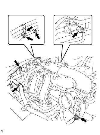
REMOVE AIR CLEANER ASSEMBLY
-
Disconnect the vacuum hose.
-
Disconnect the MAF meter connector.
-
Remove the 2 wire harness clamps.
-
Loosen the 2 hose clamps.
-
Remove the 2 bolts and air cleaner.
-
-
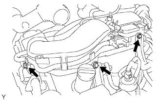
REMOVE INTAKE AIR SURGE TANK
-
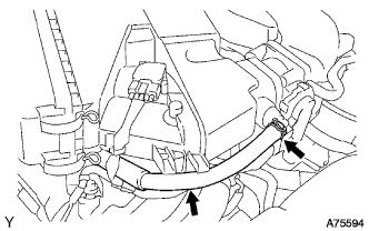
Disconnect the No. 5 water by-pass hose.
-
Disconnect the No. 4 water by-pass hose.
-
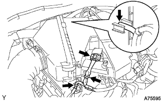
Disconnect the fuel vapor feed hose assembly.
-
Disconnect the ventilation hose.
-
Disconnect the 2 VSV connectors.
-
Disconnect the throttle motor connector.
-
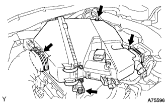
Remove the 3 wire harness clamps and hose clamp.
-
Remove the 3 upper bolts, which are used to secure the 2 surge tank stays and throttle body bracket.
-
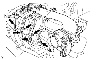
Using an 8 mm hexagon wrench, remove the 4 bolts.
-
Remove the 2 nuts, intake air surge tank and gasket.
-
-
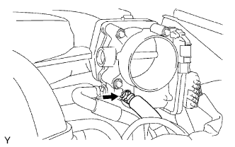
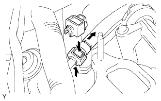
DISCONNECT NO. 2 FUEL PIPE SUB-ASSEMBLY
-
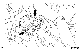
Remove the fuel pipe clamp.
-
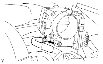
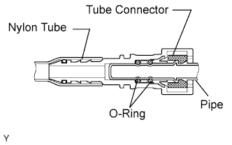
Pinch the tube connector and then pull out the fuel pipe.
Note
-
-
Check if there is any dirt or mud around the connector before this procedure, Clean if necessary. Foreign matter can affect the quick connector O-ring's seal between the fuel pipe and fuel delivery pipe.
-
Do not use any tool in this procedure.
-
Do not bend or twist the nylon tube.
-
Keep the plug free from foreign objects.
-
To protect the fuel pipe, cover it with a plastic bag after checking.
-
When the fuel pipe and fuel pressure regulator are stuck, pinch the nylon tube with fingers, and turn it carefully to free and then disconnect the fuel pipe.
-
-
-
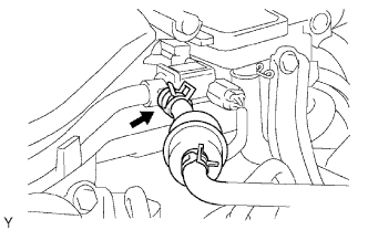
REMOVE FUEL PRESSURE REGULATOR ASSEMBLY
-
Remove the 2 bolts and fuel pressure regulator.
-
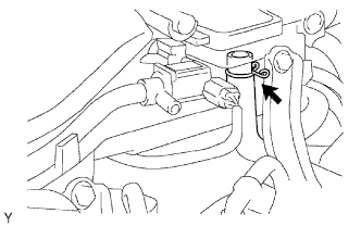
Remove the vacuum hose.
-