FIT STANDARD / ADJUSTMENT METHOD ADJUSTMENT
-
INSPECT HOOD SUB-ASSEMBLY
-
Check that the clearance measurements of areas A to D are within the standard ranges.
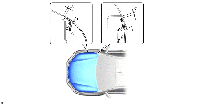
Tech Tips
Centering bolts are used to mount the hood hinge to the vehicle body and hood. The hood cannot be adjusted with the centering bolts on. Substitute the centering bolts for standard bolts when making adjustments.
-
-
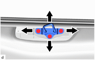
ADJUST HOOD SUB-ASSEMBLY
-
Adjust the hood position.
-
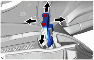
Loosen the 4 hinge bolts on the hood and adjust the hood position.
-
Move the hood and adjust the clearance between the hood and front fender.
-
Tighten the 4 hinge bolts on the hood after the adjustment.
- Torque:
- 13 N*m { 133 kgf*cm, 10 ft.*lbf }
-
-
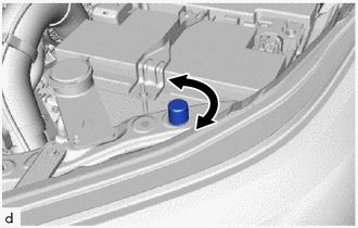
Adjust the cushion rubbers so that the hood and fender are aligned.
Tech Tips
Raise or lower the front end of the hood by turning the cushion rubber.
-
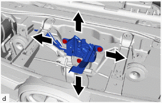
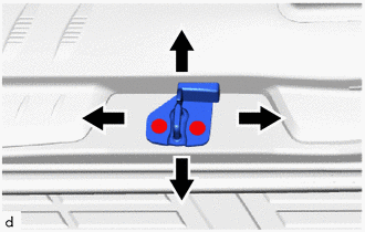
Adjust the hood lock.
-
Loosen the 3 bolts.
-
Adjust the hood lock position so that the striker can enter it smoothly.
-
Tighten the 3 bolts after the adjustment.
- Torque:
- 11 N*m { 112 kgf*cm, 8 ft.*lbf }
-
-
-
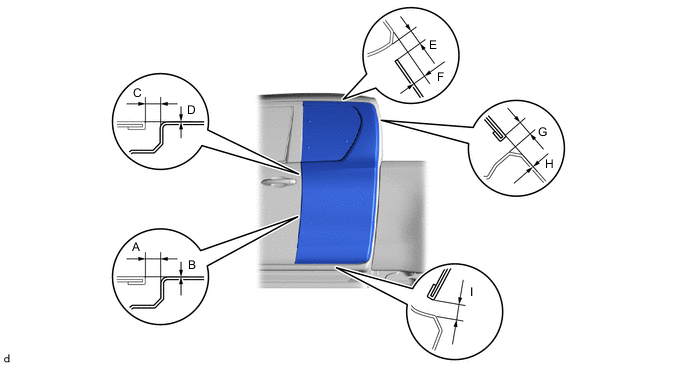
INSPECT FRONT DOOR PANEL SUB-ASSEMBLY LH
-
Check that the clearance measurements of areas A to J are within the standard ranges.
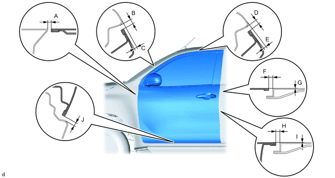
*1: for Single Cab, Smart Cab
*2: for Smart Cab, Double Cab
*3: for Single Cab
*4: for Double Cab
Tech Tips
-
Use the same procedure for the RH and LH sides.
-
The procedure listed below is for the LH side.
-
Centering bolts are used to mount the door hinge to the vehicle body and door. The door cannot be adjusted with the centering bolts on. Substitute the centering bolts for standard bolts when making adjustments.
-
-
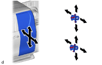
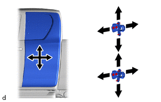
ADJUST FRONT DOOR PANEL SUB-ASSEMBLY LH
-
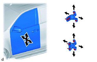
Using SST, loosen the hinge bolts on the body and adjust the door position.
- SST
- 09812-00010
-
Tighten the hinge bolts on the body after the adjustment.
- Torque:
- 26 N*m { 265 kgf*cm, 19 ft.*lbf }
-
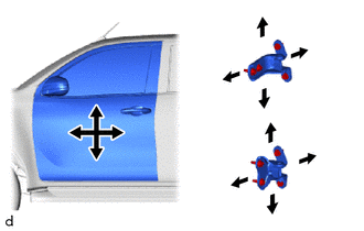
Loosen the hinge bolts on the door and adjust the door position.
-
Tighten the hinge bolts on the door after the adjustment.
- Torque:
- 21 N*m { 214 kgf*cm, 15 ft.*lbf }
-
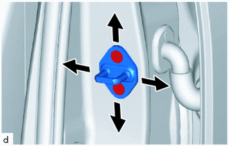
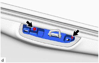
Using a T40 "TORX" socket wrench, adjust the striker position by slightly loosening the striker mounting screws and hitting the striker with a plastic-faced hammer.
-
Using a T40 "TORX" socket wrench, tighten the striker mounting screws after the adjustment.
- Torque:
- 23 N*m { 235 kgf*cm, 17 ft.*lbf }
-
-
INSPECT REAR DOOR PANEL SUB-ASSEMBLY LH (for Double Cab)
-
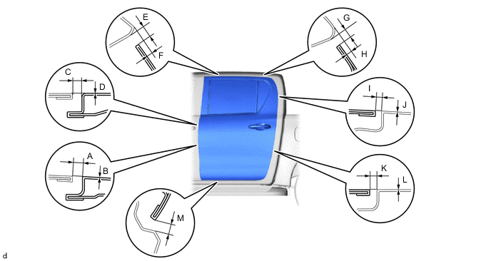
Check that the clearance measurements of areas A to M are within the standard ranges.
Tech Tips
-
Use the same procedure for the RH and LH sides.
-
The procedure listed below is for the LH side.
-
Centering bolts are used to mount the door hinge to the vehicle body and door. The door cannot be adjusted with the centering bolts on. Substitute the centering bolts for standard bolts when making adjustments.
-
-
ADJUST REAR DOOR PANEL SUB-ASSEMBLY LH (for Double Cab)
-
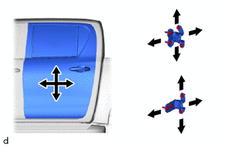
Using SST, loosen the hinge bolts on the body and adjust the door position.
- SST
- 09812-00010
-
Tighten the hinge bolts on the body after the adjustment.
- Torque:
- 26 N*m { 265 kgf*cm, 19 ft.*lbf }
-
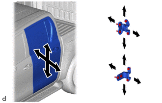
Loosen the hinge bolts on the door and adjust the door position.
-
Tighten the hinge bolts on the door after the adjustment.
- Torque:
- 21 N*m { 214 kgf*cm, 15 ft.*lbf }
-
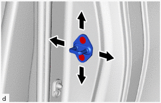
Using a T40 "TORX" socket wrench, adjust the striker position by slightly loosening the striker mounting screws and hitting the striker with a plastic-faced hammer.
- Torque:
- 23 N*m { 235 kgf*cm, 17 ft.*lbf }
-
-
INSPECT ACCESS PANEL PANEL SUB-ASSEMBLY LH (for Smart Cab)
-
Check that the clearance measurements of areas A to I are within the standard ranges.
Tech Tips
-
Use the same procedure for the RH and LH sides.
-
The procedure listed below is for the LH side.
-
Centering bolts are used to mount the door hinge to the vehicle body and door. The door cannot be adjusted with the centering bolts on. Substitute the centering bolts for standard bolts when making adjustments.
-
-
ADJUST ACCESS PANEL PANEL SUB-ASSEMBLY LH (for Smart Cab)
-
Using SST, loosen the hinge bolts on the body and adjust the access panel position.
- SST
- 09812-00010
-
Tighten the hinge bolts on the body after the adjustment.
- Torque:
- 26 N*m { 265 kgf*cm, 19 ft.*lbf }
-
Loosen the hinge bolts on the access panel and adjust the access panel position.
-
Tighten the hinge bolts on the access panel after the adjustment.
- Torque:
- 26 N*m { 265 kgf*cm, 19 ft.*lbf }
-
Remove the roof side rail garnish LH
-
Remove the 2 screws and roof side rail garnish insert LH.
-
Using a T40 "TORX" socket wrench, adjust the striker position by slightly loosening the striker mounting screws and hitting the striker with a plastic-faced hammer and brass bar.
- Torque:
- 23 N*m { 235 kgf*cm, 17 ft.*lbf }
-
Using a T40 "TORX" socket wrench, adjust the striker position by slightly loosening the striker mounting screws and hitting the striker with a plastic-faced hammer.
- Torque:
- 23 N*m { 235 kgf*cm, 17 ft.*lbf }
-
Install the roof side rail garnish insert LH with the 2 screws.
-
Install the roof side rail garnish LH.
-
-
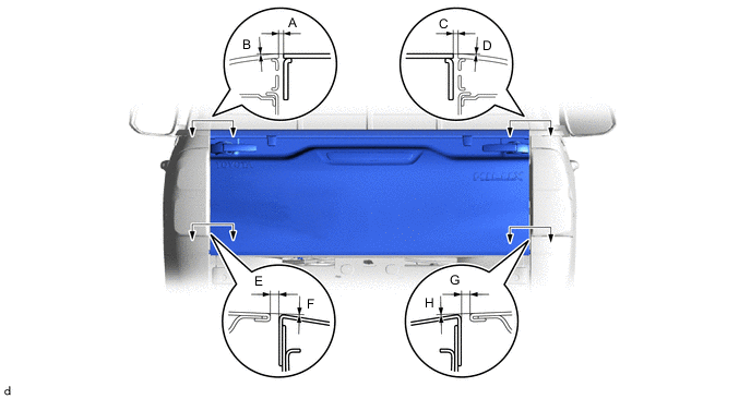
INSPECT REAR BODY TAIL GATE ASSEMBLY (for A Deck)
-
Check that the clearance measurements of areas A to H are within the standard ranges.
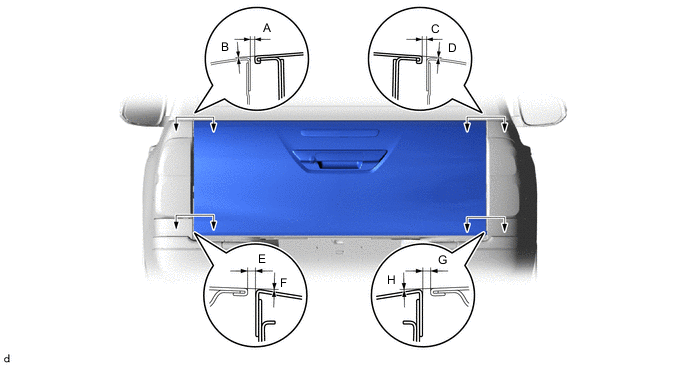
*1: for Standard Body
*2: for Wide Body
-
-
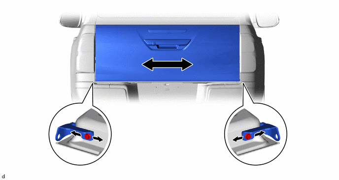
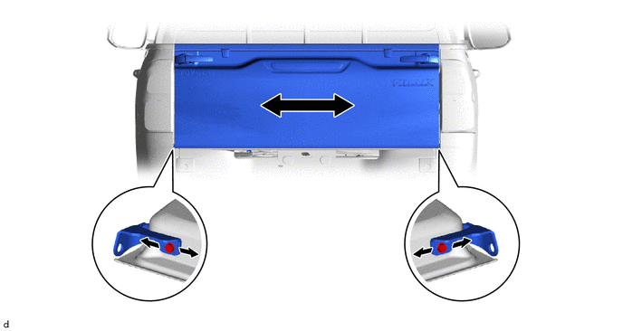
ADJUST REAR BODY TAIL GATE ASSEMBLY (for A Deck)
-
Loosen the hinge bolts on the rear body tail gate assembly.
-
Adjust the rear body tail gate assembly by moving it left and right so that the clearance measurements are within the specified ranges.
-
Tighten the hinge bolts on the rear body tail gate assembly after the adjustment.
- Torque:
- 25 N*m { 255 kgf*cm, 18 ft.*lbf }
-
-
INSPECT REAR BODY TAIL GATE ASSEMBLY (for J Deck)
-
Check that the clearance measurements of areas A to H are within the standard ranges.
*1: for Standard Body
*2: for Wide Body
-
-
ADJUST REAR BODY TAIL GATE ASSEMBLY (for J Deck)
-
Loosen the hinge bolts on the rear body tail gate assembly.
-
Adjust the rear body tail gate assembly by moving it left and right so that the clearance measurements are within the specified ranges.
-
Tighten the hinge bolts on the rear body tail gate assembly after the adjustment.
- Torque:
- 25 N*m { 255 kgf*cm, 18 ft.*lbf }
-