REAR POWER SEAT CONTROL SYSTEM(for Third Row) Position Sensor Circuit
DESCRIPTION
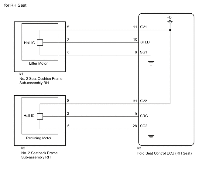
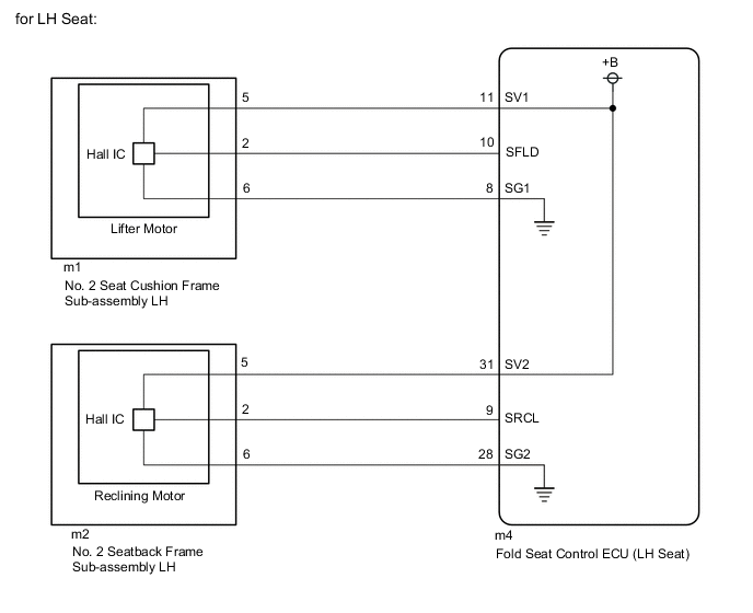
When a fold seat control ECU receives signals from the fold seat switch assembly or No. 1 fold seat switch assembly, it operates the reclining motor and lifter motor of its corresponding rear No. 2 power seat. When the reclining motor or lifter motor is operating, the position sensor (Hall IC) in it outputs signals. These signals are received by the corresponding fold seat control ECU, which uses them to detect the position of the seatback and seat cushion.
WIRING DIAGRAM
CAUTION / NOTICE / HINT
Note
-
When a fold seat control ECU (RH/LH seat) is replaced, it is necessary to perform initialization.
-
When No. 2 seat cushion frame sub-assembly RH, No. 2 seat cushion frame sub-assembly LH, No. 2 seatback frame sub-assembly RH or No. 2 seatback frame sub-assembly LH is removed and reinstalled, it is necessary to perform initialization.
PROCEDURE
-
CHECK REAR POWER SEAT CONTROL SYSTEM (for Third Row)
-
Check that the rear power seat control system (for Third Row) function operates normally.
Result Result Proceed to Fold/Return functions of rear No. 2 power seat RH do not operate normally. A Fold/Return functions of rear No. 2 power seat LH do not operate normally. B
B 
CHECK FOLD SEAT CONTROL ECU (LH SEAT) (SENSOR POWER SOURCE) Click here
A 
-
-
CHECK FOLD SEAT CONTROL ECU (RH SEAT) (SENSOR POWER SOURCE)
-
Disconnect the k1 No. 2 seat cushion frame sub-assembly RH connector.
-
Disconnect the k2 No. 2 seatback frame sub-assembly RH connector.
-
Measure the voltage according to the value(s) in the table below.
Standard Voltage Lifter Motor Tester Connection Condition Specified Condition k1-5 - k1-6 Fold switch (RH) of fold seat switch assembly or No. 1 fold seat switch assembly pushed 5.5 to 10 V Reclining Motor Tester Connection Condition Specified Condition k2-5 - k2-6 Return switch (RH) of fold seat switch assembly or No. 1 fold seat switch assembly pushed 5.5 to 10 V Result Proceed to OK NG
NG
CHECK HARNESS AND CONNECTOR (NO. 2 SEAT CUSHION FRAME SUB-ASSEMBLY RH AND NO. 2 SEATBACK FRAME SUB-ASSEMBLY RH - FOLD SEAT CONTROL ECU (RH SEAT)) Click here
OK
-
-
CHECK NO. 2 SEAT CUSHION FRAME SUB-ASSEMBLY RH (SENSOR SIGNAL)
-
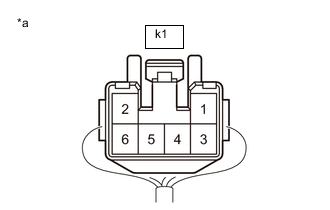
*a Component with harness connected
(No. 2 Seat Cushion Frame Sub-assembly RH (Lifter Motor))
Reconnect the k1 No. 2 seat cushion frame sub-assembly RH connector.
-
Using an oscilloscope, check the waveform.
OK Tester Connection Condition Specified Condition k1-2 - Body ground Lifter motor operating Pulse generation
(Hi: 5.5 to 10 V, Lo: Below 1 V)
Result Proceed to OK NG
NG
CHECK HARNESS AND CONNECTOR (NO. 2 SEAT CUSHION FRAME SUB-ASSEMBLY RH - FOLD SEAT CONTROL ECU (RH SEAT)) Click here
OK
-
-
CHECK NO. 2 SEATBACK FRAME SUB-ASSEMBLY RH (SENSOR SIGNAL)
-

*a Component with harness connected
(No. 2 Seatback Frame Sub-assembly RH (Reclining Motor))
Reconnect the k2 No. 2 seatback frame sub-assembly RH connector.
-
Using an oscilloscope, check the waveform.
OK Tester Connection Condition Specified Condition k2-2 - Body ground Reclining motor operation Pulse generation
(Hi: 5.5 to 10 V, Lo: Below 1 V)
Result Proceed to OK NG
OK 
PROCEED TO NEXT SUSPECTED AREA SHOWN IN PROBLEM SYMPTOMS TABLE Click here
NG
CHECK HARNESS AND CONNECTOR (NO. 2 SEATBACK FRAME SUB-ASSEMBLY RH - FOLD SEAT CONTROL ECU (RH SEAT)) Click here
-
-
CHECK HARNESS AND CONNECTOR (NO. 2 SEAT CUSHION FRAME SUB-ASSEMBLY RH AND NO. 2 SEATBACK FRAME SUB-ASSEMBLY RH - FOLD SEAT CONTROL ECU (RH SEAT))
-
Disconnect the k3 fold seat control ECU (RH seat) connector.
-
Measure the resistance according to the value(s) in the table below.
Standard Resistance Lifter Motor Tester Connection Condition Specified Condition k1-5 - k3-11 (SV1) Always Below 1 Ω k1-5 or k3-11 (SV1) - Body ground Always 10 kΩ or higher k1-6 - k3-8 (SG1) Always Below 1 Ω k1-6 or k3-8 (SG1) - Body ground Always 10 kΩ or higher Reclining Motor Tester Connection Condition Specified Condition k2-5 - k3-31 (SV2) Always Below 1 Ω k2-5 or k3-31 (SV2) - Body ground Always 10 kΩ or higher k2-6 - k3-28 (SG2) Always Below 1 Ω k2-6 or k3-28 (SG2) - Body ground Always 10 kΩ or higher Result Proceed to OK NG
OK
REPLACE FOLD SEAT CONTROL ECU (RH SEAT) Click here
NG
REPAIR OR REPLACE HARNESS OR CONNECTOR
-
-
CHECK HARNESS AND CONNECTOR (NO. 2 SEAT CUSHION FRAME SUB-ASSEMBLY RH - FOLD SEAT CONTROL ECU (RH SEAT))
-
Disconnect the k3 fold seat control ECU (RH seat) connector.
-
Measure the resistance according to the value(s) in the table below.
Standard Resistance Tester Connection Condition Specified Condition k1-2 - k3-10 (SFLD) Always Below 1 Ω k1-2 or k3-10 (SFLD) - Body ground Always 10 kΩ or higher Result Proceed to OK NG
OK
REPLACE FOLD SEAT CONTROL ECU (RH SEAT) Click here
NG
REPAIR OR REPLACE HARNESS OR CONNECTOR
-
-
CHECK HARNESS AND CONNECTOR (NO. 2 SEATBACK FRAME SUB-ASSEMBLY RH - FOLD SEAT CONTROL ECU (RH SEAT))
-
Disconnect the k3 fold seat control ECU (RH seat) connector.
-
Measure the resistance according to the value(s) in the table below.
Standard Resistance Tester Connection Condition Specified Condition k2-2 - k3-9 (SRCL) Always Below 1 Ω k2-2 or k3-9 (SRCL) - Body ground Always 10 kΩ or higher Result Proceed to OK NG
OK
REPLACE FOLD SEAT CONTROL ECU (RH SEAT) Click here
NG
REPAIR OR REPLACE HARNESS OR CONNECTOR
-
-
CHECK FOLD SEAT CONTROL ECU (LH SEAT) (SENSOR POWER SOURCE)
-
Disconnect the m1 No. 2 seat cushion frame sub-assembly LH connector.
-
Disconnect the m2 No. 2 seatback frame sub-assembly LH connector.
-
Measure the voltage according to the value(s) in the table below.
Standard Voltage Lifter Motor Tester Connection Condition Specified Condition m1-5 - m1-6 Fold switch (LH) of fold seat switch assembly or No. 1 fold seat switch assembly pushed 5.5 to 10 V Reclining Motor Tester Connection Condition Specified Condition m2-5 - m2-6 Return switch (LH) of fold seat switch assembly or No. 1 fold seat switch assembly pushed 5.5 to 10 V Result Proceed to OK NG
NG
CHECK HARNESS AND CONNECTOR (NO. 2 SEAT CUSHION FRAME SUB-ASSEMBLY LH AND NO. 2 SEATBACK FRAME SUB-ASSEMBLY LH - FOLD SEAT CONTROL ECU (LH SEAT)) Click here
OK
-
-
CHECK NO. 2 SEAT CUSHION FRAME SUB-ASSEMBLY LH (SENSOR SIGNAL)
-
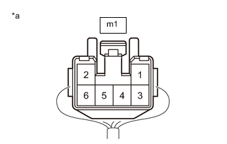
*a Component with harness connected
(No. 2 Seat Cushion Frame Sub-assembly LH (Lifter Motor))
Reconnect the m1 No. 2 seat cushion frame sub-assembly LH connector.
-
Using an oscilloscope, check the waveform.
OK Tester Connection Condition Specified Condition m1-2 - Body ground Lifter motor operation Pulse generation
(Hi: 5.5 to 10 V, Lo: Below 1 V)
Result Proceed to OK NG
NG
CHECK HARNESS AND CONNECTOR (NO. 2 SEAT CUSHION FRAME SUB-ASSEMBLY LH - FOLD SEAT CONTROL ECU (LH SEAT)) Click here
OK
-
-
CHECK NO. 2 SEATBACK FRAME SUB-ASSEMBLY LH (SENSOR SIGNAL)
-

*a Component with harness connected
(No. 2 Seatback Frame Sub-assembly LH (Reclining Motor))
Reconnect the m2 No. 2 seatback frame sub-assembly RH connector.
-
Using an oscilloscope, check the waveform.
OK Tester Connection Condition Specified Condition m2-2 - Body ground Reclining motor operation Pulse generation
(Hi: 5.5 to 10 V, Lo: Below 1 V)
Result Proceed to OK NG
OK
PROCEED TO NEXT SUSPECTED AREA SHOWN IN PROBLEM SYMPTOMS TABLE Click here
NG
CHECK HARNESS AND CONNECTOR (NO. 2 SEATBACK FRAME SUB-ASSEMBLY LH - FOLD SEAT CONTROL ECU (LH SEAT)) Click here
-
-
CHECK HARNESS AND CONNECTOR (NO. 2 SEAT CUSHION FRAME SUB-ASSEMBLY LH AND NO. 2 SEATBACK FRAME SUB-ASSEMBLY LH - FOLD SEAT CONTROL ECU (LH SEAT))
-
Disconnect the m4 fold seat control ECU (LH seat) connector.
-
Measure the resistance according to the value(s) in the table below.
Standard Resistance Lifter Motor Tester Connection Condition Specified Condition m1-5 - m4-11 (SV1) Always Below 1 Ω m1-5 or m4-11 (SV1) - Body ground Always 10 kΩ or higher m1-6 - m4-8 (SG1) Always Below 1 Ω m1-6 or m4-8 (SG1) - Body ground Always 10 kΩ or higher Reclining Motor Tester Connection Condition Specified Condition m2-5 - m4-31 (SV2) Always Below 1 Ω m2-5 or m4-31 (SV2) - Body ground Always 10 kΩ or higher m2-6 - m4-28 (SG2) Always Below 1 Ω m2-6 or m4-28 (SG2) - Body ground Always 10 kΩ or higher Result Proceed to OK NG
OK
REPLACE FOLD SEAT CONTROL ECU (LH SEAT) Click here
NG
REPAIR OR REPLACE HARNESS OR CONNECTOR
-
-
CHECK HARNESS AND CONNECTOR (NO. 2 SEAT CUSHION FRAME SUB-ASSEMBLY LH - FOLD SEAT CONTROL ECU (LH SEAT))
-
Disconnect the m4 fold seat control ECU (LH seat) connector.
-
Measure the resistance according to the value(s) in the table below.
Standard Resistance Tester Connection Condition Specified Condition m1-2 - m4-10 (SFLD) Always Below 1 Ω m1-2 or m4-10 (SFLD) - Body ground Always 10 kΩ or higher Result Proceed to OK NG
OK
REPLACE FOLD SEAT CONTROL ECU (LH SEAT) Click here
NG
REPAIR OR REPLACE HARNESS OR CONNECTOR
-
-
CHECK HARNESS AND CONNECTOR (NO. 2 SEATBACK FRAME SUB-ASSEMBLY LH - FOLD SEAT CONTROL ECU (LH SEAT))
-
Disconnect the m4 fold seat control ECU (LH seat) connector.
-
Measure the resistance according to the value(s) in the table below.
Standard Resistance Tester Connection Condition Specified Condition m2-2 - m4-9 (SRCL) Always Below 1 Ω m2-2 or m4-9 (SRCL) - Body ground Always 10 kΩ or higher Result Proceed to OK NG
OK
REPLACE FOLD SEAT CONTROL ECU (LH SEAT) Click here
NG
REPAIR OR REPLACE HARNESS OR CONNECTOR
-