МАСЛЯНЫЙ НАСОС УСТАНОВКА
-
INSTALL TIMING CHAIN COVER OIL SEAL
-
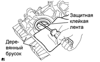
Поместите крышку цепного привода газораспределительного механизма на деревянные бруски.
-
Обернув конец отвертки изолентой, снимите сальник.
-
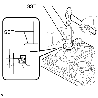
При помощи SST и молотка запрессуйте новый сальник так, чтобы его поверхность была заподлицо с краем крышки цепного привода газораспределительного механизма.
- SST
- 09223-75010
- 09950-70010 ( 09951-07150 )
Note
-
Не допускайте попадания на кромку посторонних материалов.
-
Не стучите по сальнику, направляя удары под углом.
Tech Tips
При установке шкива коленчатого вала проверьте форму шкива. Пригодный шкив имеет канавку (см. стр. Click here).
-
Нанесите тонкий слой универсальной консистентной смазки на кромку нового сальника.
-
-
INSTALL WATER PUMP
-
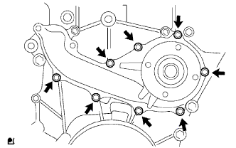
Install a new gasket and the water pump with the 8 bolts.
- Torque:
- 13 N*m { 133 kgf*cm, 10 ft.*lbf }
-
-
INSTALL TIMING CHAIN COVER (OIL PUMP BODY)
-
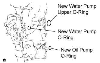
Install 3 new O-rings to the timing chain cover as shown in the illustration.
-
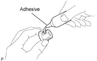
Apply adhesive to the timing gear case plug.
Adhesive Toyota Genuine Adhesive 1324, Three Bond 1324 or equivalent -
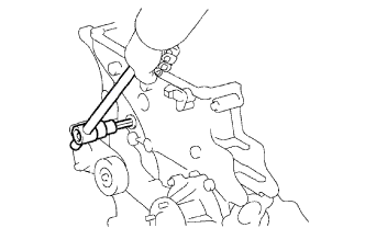
Using a 10 mm socket hexagon wrench, install the timing gear case plug.
- Torque:
- 16.6 N*m { 169 kgf*cm, 12 ft.*lbf }
-
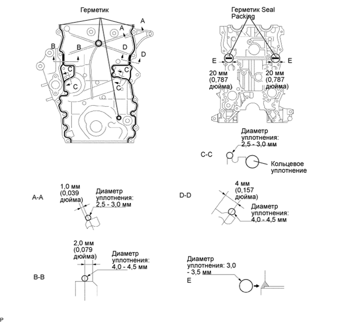
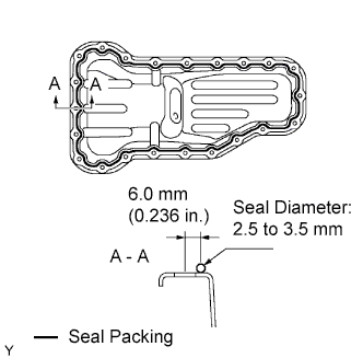
Apply seal packing in a continuous line as shown in the illustration.
Seal packing Toyota Genuine Seal Packing Black, Three Bond 1207B or equivalent Seal diameter Position Specified Condition A - A, C - C 2.5 to 3.0 mm (0.098 to 0.118 in.) B - B, D - D 4.0 to 4.5 mm (0.157 to 0.177 in.) E 3.0 to 3.5 mm (0.118 to 0.138 in.) Note
-
Remove any oil from the contact surface.
-
Install the timing chain cover within 3 minutes and tighten the bolts within 15 minutes after applying seal packing.
-
Do not start the engine for at least 4 hours after the installation.
-
-
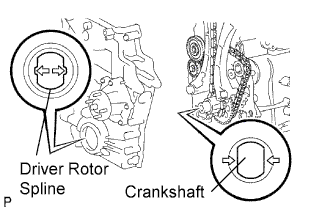
Align the oil pump's drive rotor spline and crankshaft as shown in the illustration. Install the spline and chain cover plate to the crankshaft.
-
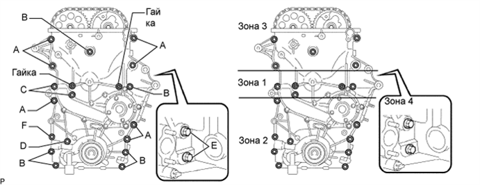
Loosely install the timing chain cover with the 19 bolts and 2 nuts, but do not tighten the bolts and nuts yet.
-
Excluding the bolts labeled A and C, tighten the bolts and nuts in this order: Area 1, Area 2 and Area 3.
- Torque:
- 21 N*m { 214 kgf*cm, 15 ft.*lbf }
Bolt Length Item Length Thread Diameter Bolt A 75 mm (2.95 in.) 10 mm (0.394 in.) Bolt B 75 mm (2.95 in.) 8 mm (0.315 in.) Bolt C 90 mm (3.54 in.) 8 mm (0.315 in.) Bolt D 95 mm (3.74 in.) 8 mm (0.315 in.) Bolt E 35 mm (1.38 in.) 8 mm (0.315 in.) Bolt F 75 mm (2.95 in.) 10 mm (0.394 in.) -
Excluding the bolts labeled A, E and F, tighten the bolts and nuts in this order: Area 1, Area 3, Area 2.
- Torque:
- for bolt C
- 26 N*m { 265 kgf*cm, 19 ft.*lbf }
- for bolt B, D and nut
- 21 N*m { 214 kgf*cm, 15 ft.*lbf }
-
Tighten the bolts labeled A in this order: Area 2 and Area 3.
- Torque:
- 60 N*m { 612 kgf*cm, 44 ft.*lbf }
-
Tighten the bolt labeled F.
- Torque:
- 46 N*m { 469 kgf*cm, 34 ft.*lbf }
-
Tighten the bolts labeled E in Area 4.
- Torque:
- 21 N*m { 214 kgf*cm, 15 ft.*lbf }
-
-
INSTALL CRANKSHAFT POSITION SENSOR
-
Apply a light coat of engine oil to the O-ring of the sensor.
-
Install the sensor with the bolt.
- Torque:
- 8.5 N*m { 87 kgf*cm, 75 in.*lbf }
-
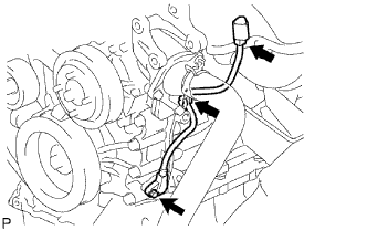
Install the connector to the connector bracket.
-
Attach the harness clamp.
-
Connect the sensor connector.
-
-
INSTALL NO. 1 OIL PAN
-
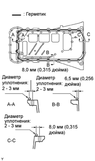
Apply seal packing in a continuous line as shown in the illustration.
Seal packing Toyota Genuine Seal Packing Black, Three Bond 1207B or equivalent Seal diameter 2 to 3 mm (0.079 to 0.118 in.) Note
-
Remove any oil from the contact surface.
-
Install the oil pan within 3 minutes after applying seal packing.
-
Do not start the engine for at least 4 hours after the installation.
-
-
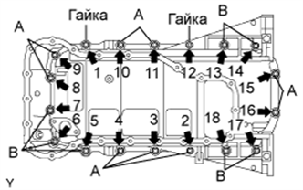
Temporarily install the oil pan with the 16 bolts and 2 nuts.
Tech Tips
Bolt length:
20 mm (0.79 in.) for bolt A
40 mm (1.57 in.) for bolt B
-
Uniformly tighten the 16 bolts and 2 nuts in the order shown in the illustration.
- Torque:
- 26 N*m { 265 kgf*cm, 19 ft.*lbf }
-
-
INSTALL OIL STRAINER
-
Install a new gasket and the oil strainer with the bolt and 2 nuts.
- Torque:
- 20 N*m { 204 kgf*cm, 15 ft.*lbf }
-
-
INSTALL NO. 2 OIL PAN
-
Apply seal packing in a continuous line as shown in the illustration.
Seal packing Toyota Genuine Seal Packing Black, Three Bond 1207B or equivalent Seal diameter 2.5 to 3.5 mm (0.098 to 0.138 in.) Note
-
Remove any oil from the contact surface.
-
Install the oil pan within 3 minutes after applying seal packing.
-
Do not start the engine for at least 4 hours after the installation.
-
-
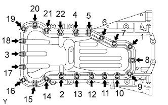
Temporarily install the oil pan with the 20 bolts and 2 nuts.
-
Uniformly tighten the 20 bolts and 2 nuts in the order shown in the illustration.
- Torque:
- 9.0 N*m { 92 kgf*cm, 80 in.*lbf }
-
Install a new gasket and the drain plug.
-
-
CHECK CRANKSHAFT PULLEY
-
Check that the crankshaft pulley matches the pulley labeled A in the illustration.
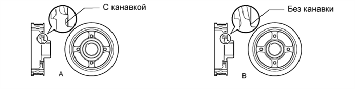
Note
If the crankshaft pulley matches the pulley labeled B, replace the crankshaft pulley.
-
-
INSTALL CRANKSHAFT PULLEY
-
Align the pulley set key with the key groove of the pulley, and slide on the pulley.
-
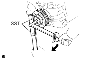
Using SST, install the crankshaft pulley bolt.
- SST
- 09213-54015 ( 91651-60855 )
- 09330-00021
- Torque:
- 260 N*m { 2,651 kgf*cm, 192 ft.*lbf }
Note
Do not reuse the pulley bolt.
-
-
INSTALL CAMSHAFT POSITION SENSOR
-
Apply a coat of engine oil to a new O-ring.
-
Install the sensor with the bolt.
- Torque:
- 8.5 N*m { 87 kgf*cm, 75 in.*lbf }
-
-
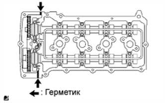
INSTALL CYLINDER HEAD COVER
-
Install the 2 cover gaskets to the head cover.
-
Apply seal packing to the places shown in the illustration.
Seal packing Toyota Genuine Seal Packing Black, Three Bond 1207B or equivalent Note
-
Remove any oil from the contact surface.
-
Install the head cover within 3 minutes after applying seal packing.
-
Do not start the engine for at least 2 hours after the installation.
-
-
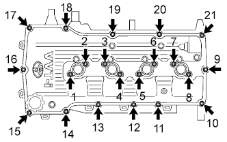
Temporarily install the head cover with the 19 bolts and 2 nuts.
-
Uniformly tighten the 19 bolts and 2 nuts in the order shown in the illustration.
- Torque:
- 9.0 N*m { 92 kgf*cm, 80 in.*lbf }
-
In numerical order, confirm that the bolts labeled 1 to 8 are tightened to the torque specification. Tighten the bolts as necessary.
-
-
INSTALL OIL FILLER CAP
-
INSTALL NO. 1 WATER BY-PASS PIPE
-
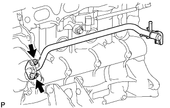
Install a new gasket and the water by-pass pipe with the 2 nuts.
- Torque:
- 17.5 N*m { 178 kgf*cm, 13 ft.*lbf }
-
-
INSTALL NO. 1 IDLER PULLEY
-
Install the spacer, idler pulley and pulley plate with the bolt.
- Torque:
- 43 N*m { 438 kgf*cm, 32 ft.*lbf }
-
-
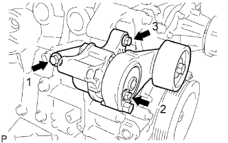
INSTALL DRIVE BELT TENSIONER
-
Temporarily install the belt tensioner with the 3 bolts.
Tech Tips
Make sure that the flanges of the bolts are contacting the tensioner surface.
-
Install the tensioner by tightening the 3 bolts in the order shown in the illustration.
- Torque:
- 40 N*m { 408 kgf*cm, 30 ft.*lbf, for bolt 1 }
- 21 N*m { 214 kgf*cm, 15 ft.*lbf, for bolt 2 }
- 43 N*m { 438 kgf*cm, 32 ft.*lbf, for bolt 3 }
-
-
INSTALL THERMOSTAT
-
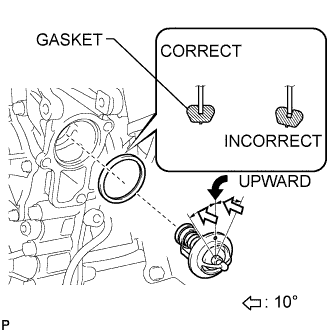
Install a new gasket to the thermostat.
Tech Tips
When installing the thermostat to the gasket, be careful not to deform the gasket. Make sure that the thermostat is properly installed into the groove of the gasket, as shown in the illustration.
-
Insert the thermostat into the cylinder block with the jiggle valve facing straight upward.
Tech Tips
The jiggle valve may be set within 10°of either side of the prescribed position.
-
-
INSTALL WATER INLET
-
Install the inlet with the 2 nuts and bolt.
- Torque:
- 20 N*m { 204 kgf*cm, 15 ft.*lbf }
-
Connect the connector.
-
-
INSTALL NO. 1 COMPRESSOR MOUNTING BRACKET (w/ Air Conditioning System)
Note
Install the No. 1 compressor mounting bracket exactly as described in the procedures below to properly secure and prevent damage to the fan and generator V belt.
-
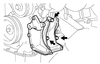
Temporarily install the No. 1 compressor mounting bracket with the 3 bolts.
Tech Tips
Temporarily install the No. 1 compressor mounting bracket with the 3 bolts so that the bracket can be moved by hand.
-
Push the No. 1 compressor mounting bracket toward the cylinder block as shown in the illustration and tighten bolt B.
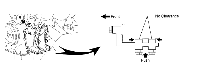
- Torque:
- 45 N*m { 459 kgf*cm, 33 ft.*lbf, for bolt B }
Tech Tips
Make sure there is no clearance between the cylinder block and No. 1 compressor mounting bracket as shown in the illustration.
-
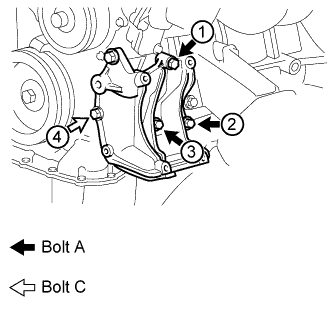
Uniformly tighten the 4 bolts in the order shown in the illustration.
- Torque:
- 45 N*m { 459 kgf*cm, 33 ft.*lbf, for bolt A }
- 24.5 N*m { 250 kgf*cm, 18 ft.*lbf, for bolt C }
-
-
INSTALL GENERATOR
-
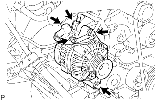
Install the generator with the 2 bolts.
- Torque:
- 43 N*m { 438 kgf*cm, 32 ft.*lbf }
-
Install the generator wire with the bolt and nut.
- Torque:
- 9.8 N*m { 100 kgf*cm, 87 in.*lbf }
-
Connect the connector.
-
-
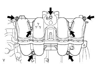
INSTALL INTAKE MANIFOLD
-
Install a new gasket and the intake manifold with the 5 bolts and 2 nuts.
- Torque:
- 25 N*m { 255 kgf*cm, 18 ft.*lbf }
-
Connect the crankshaft position sensor to the clamp.
-
-
INSTALL THROTTLE BODY
-
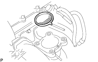
Install a new gasket on the intake manifold.
Tech Tips
Align the protrusion of the gasket with the groove of the intake manifold.
-
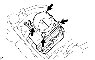
Install the throttle body with the 4 bolts.
- Torque:
- 9.0 N*m { 92 kgf*cm, 80 in.*lbf }
-
Connect the 2 water by-pass hoses to the throttle body.
-
Connect the throttle position sensor and control motor connector.
-
-
INSTALL SPARK PLUG
-
INSTALL IGNITION COIL
-
Install the ignition coil with the bolt.
-
-
REMOVE ENGINE ASSEMBLY FROM ENGINE STAND
-
INSTALL ENGINE ASSEMBLY
-
Install the engine to the vehicle Click here.
-
-
CONNECT CABLE TO NEGATIVE BATTERY TERMINAL
-
ADD ENGINE OIL
-
Clean and install the oil drain plug with a new gasket.
- Torque:
- 37.5 N*m { 382 kgf*cm, 28 ft.*lbf }
-
Add fresh engine oil.
Standard capacity Item Capacity Drain and refill with oil filter change 5.6 liters (5.9 US qts, 4.9 Imp. qts) Drain and refill without oil filter change 5.3 liters (5.6 US qts, 4.7 Imp. qts) Dry fill 6.3 liters (6.7 US qts, 5.5 Imp. qts) -
Install the oil filler cap.
-
-
ADD ENGINE COOLANT
-
Tighten all the plugs and fill the radiator with TOYOTA Super Long Life Coolant (SLLC).
- Torque:
- 13 N*m { 133 kgf*cm, 10 ft.*lbf, for cylinder block drain cock plug }
Standard capacity Item Specified Condition Manual transmission w/ Heater 7.8 liters (8.2 US qts, 6.9 Imp. qts) w/o Heater 7.0 liters (7.4 US qts, 6.2 Imp. qts) Automatic transmission w/ Heater 8.1 liters (8.6 US qts, 7.1 Imp. qts) w/o Heater 7.3 liters (7.7 US qts, 6.4 Imp. qts) -
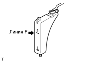
Fill the radiator reservoir with TOYOTA Super Long Life Coolant (SLLC) to the F line.
Tech Tips
-
TOYOTA vehicles are filled with TOYOTA SLLC at the factory. In order to avoid damage to the engine cooling system and other technical problems, only use TOYOTA SLLC or similar high quality ethylene glycol based non-silicate, non-amine, non-nitrite, non-borate coolant with long-life hybrid organic acid technology (coolant with long-life hybrid organic acid technology is a combination of low phosphates and organic acids).
-
Please contact your TOYOTA dealer for further details.
Note
Never use water as a substitute for engine coolant.
-
-
Press the inlet and outlet radiator hoses several times by hand, and then check the level of the coolant.
If the coolant level drops below the F line, add TOYOTA SLLC to the F line.
-
Install the radiator cap.
-
Bleed air from the cooling system.
-
Warm up the engine until the thermostat opens. While the thermostat is open, circulate the coolant for several minutes.
-
Maintain the engine speed at 2,500 to 3,000 rpm.
-
Press the inlet and outlet radiator hoses several times by hand to bleed air.
CAUTION:
When pressing the radiator hoses:
-
Wear protective gloves.
-
Be careful as the radiator hoses are hot.
-
Keep your hands away from the radiator fan.
-
-
-
Stop the engine and wait until the coolant cools down to ambient temperature.
CAUTION:
Do not remove the radiator cap while the engine and radiator are still hot. Pressurized, hot engine coolant and steam may be released and cause serious burns.
-
Check the coolant level in the radiator reservoir.
If the coolant level is below the L line, add SLLC to the reservoir F line.
-
-
CHECK FUEL FOR LEAKS
-
Connect the intelligent tester to the DLC3.
-
Turn the ignition switch ON.
Note
Do not start the engine.
-
Push the intelligent tester main switch ON.
-
Select the Active Test and enter the following menus: Powertrain / Engine and ECT / Active Test / Control the Fuel Pump / Speed.
-
-
Check for fuel leaks.
-
Check that there are no fuel leaks after performing maintenance anywhere on the fuel system.
-
-
-
CHECK FOR OIL LEAKS
-
Start the engine, and check that there are no oil leaks after performing maintenance.
-
-
CHECK FOR COOLANT LEAKS
CAUTION:
Не снимайте пробку радиатора, пока двигатель и радиатор не остынут. Выброс горячей охлаждающей жидкости и пара под давлением может стать причиной серьезных ожогов.
-
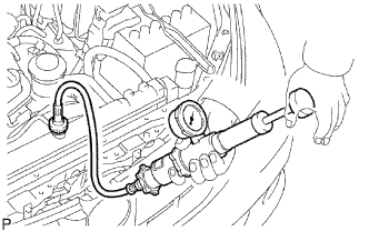
Заполните радиатор охлаждающей жидкостью и подсоедините приспособление для опрессовки системы охлаждения и проверки пробки радиатора.
-
Прогрейте двигатель.
-
С помощью приспособления для опрессовки системы охлаждения и проверки пробки радиатора увеличьте давление в радиаторе до 118 кПа (1,2 кгс/см2, 17,1 фунтов на кв. дюйм) и убедитесь, что давление не падает.
Если давление снижается, проверьте на наличие утечек шланги, радиатор и насос системы охлаждения. При отсутствии внешних утечек проверьте блок цилиндров и головку блока цилиндров.
-
-
CHECK IDLE SPEED AND IGNITION TIMING
-
Warm up and stop the engine.
Note
A warmed up engine should have an engine coolant temperature of over 80°C (176°F), have an engine oil temperature of 60°C (140°F), and the engine rpm should be stabilized.
-
Check the idle speed control system.
-
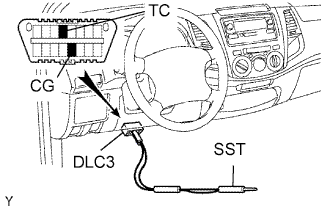
Using SST, connect terminals TC and CG of the DLC3.
- SST
- 09843-18040
-
Start the engine at idle.
Note
-
Confirm the terminal numbers before connecting them. Connection with a wrong terminal can damage the engine.
-
Turn off all electrical systems before connecting the terminals.
-
When checking ISC function, the transmission should be in the neutral position.
-
-
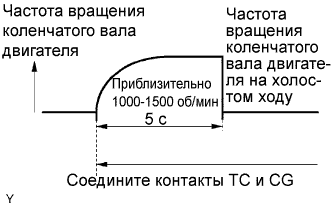
After connecting terminals (TC and CG), check that the engine speed changes to approximately 1,000 to 1,500 rpm for 5 seconds, and then returns to idle speed.
If the result is not as specified, check the throttle body, DTC Click here and wire harness.
-
-
-
CHECK CO (for Leaded Gasoline Specification Vehicle)
Tech Tips
This check is used only to determine whether or not the idle CO complies with regulations.
-
Initial condition:
-
Engine at normal operating temperature
-
Air cleaner installed
-
All pipes and hoses of air induction system connected
-
All accessories switched OFF
-
All vacuum lines properly connected
-
SFI system wiring connectors fully seated
-
Ignition timing set correctly
-
Transmission in neutral position
-
Tachometer and CO meter calibration at idle
Note
If a CO meter is not available, do not attempt to adjust the idle mixture. Always use a CO meter when adjusting the idle mixture. Use of the idle mixture screw for adjustments is typically not necessary if the vehicle is in good condition.
-
-
Warm up the engine under constant speed (approximately 50 km/h (31 mph)). Close the throttle valve for 5 minutes after the engine coolant temperature becomes stable (80 to 90°C (176 to 194°F)) and idle the engine for 5 minutes.
-
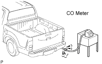
Insert a tester probe at least 40 cm (1.3 ft.) into the tailpipe.
-
Wait at least 1 minute before measuring to allow the concentration to stabilize. Complete the measuring within 3 minutes.
Standard idle CO concentration 1.0 to 2.5 % -
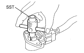
If the CO concentration does not conform to regulations, adjust by turning the idle mixture adjusting screw in the variable resistor with SST.
- SST
- 09243-00020
-
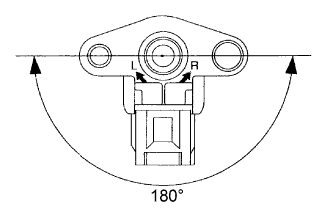
The idle mixture adjusting screw can be adjusted through an 180° angle range.
If the CO concentration is within specification, this adjustment is complete.
If the CO concentration cannot be corrected by idle mixture adjustment, see the table below for other possible causes.
CO Problems Causes High Rough idle
(black smoke from exhaust)
-
Clogged air filter
-
Plugged ventilation valve
-
Faulty SFI system
-
Faulty fuel pressure regulator
-
Clogged fuel pressure regulator
-
Defective engine coolant temperature (ECT) sensor
-
Faulty ECM
-
Faulty injectors
-
Faulty throttle position sensor
-
Faulty MAF meter
-
-
-
CHECK CO/HC (for Unleaded Gasoline Specification Vehicle)
-
Start and warm up the engine.
-
Run the engine at 2,500 rpm for approximately 180 seconds and idle the engine.
-
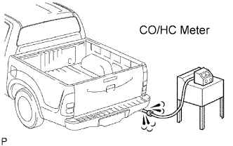
Insert CO/HC meter testing probe at least 40 cm (1.3 ft.) into the tailpipe.
-
Check CO/HC concentration at idle.
Standard idle CO concentration 0 to 0.5 % Standard idle HC concentration Applicable local regulation -
If the CO/HC concentration is not as specified, perform troubleshooting in the order given below.
-
Check the heated oxygen sensor operation Click here.
-
See the table below for possible causes, and then inspect and repair the applicable causes if necessary.
CO HC Problems Causes Normal High Rough idle
-
Faulty ignitions:
-
Incorrect timing
-
Plugs are contaminated, shorted or gaps are defective
-
Incorrect valve clearance
-
Leaks in intake and exhaust valves
-
Leaks in cylinders
Low High Rough idle
(Fluctuating HC reading)
-
Vacuum leaks:
-
PCV hoses
-
Intake manifold
-
Throttle body
-
Brake booster line
-
Lean mixture causing misfire
High High Rough idle
(Black smoke from exhaust)
-
Restricted air filter
-
Plugged PCV valve
-
Faulty SFI system:
-
Faulty pressure regulator
-
Defective ECT sensor
-
Defective Mass Air Flow (MAF) meter
-
Faulty ECM
-
Faulty injectors
-
Faulty throttle position sensor
-
-
-
-
CHECK FUNCTION OF THROTTLE BODY
-
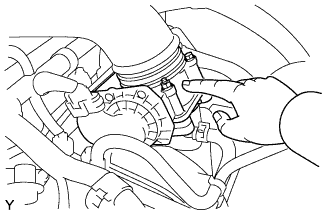
Проверьте, слышен ли звук работающего электродвигателя привода дроссельной заслонки.
-
Включите зажигание.
-
Нажимая педаль акселератора, убедитесь в наличии звука работающего двигателя. Убедитесь, что двигатель не создает шум трения.
Если слышен шум трения, замените корпус дроссельной заслонки.
-
-
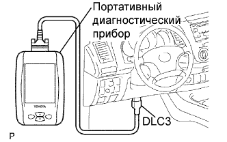
Проверьте датчик положения дроссельной заслонки.
-
Подсоедините портативный диагностический прибор к DLC3.
-
Включите зажигание.
-
Убедитесь, что в режиме Current Data процентное значение угла поворота дроссельной заслонки (Throttle Pos) не выходит за пределы номинального диапазона.
Номинальное значение открывания дроссельной заслонки 60% или более Note
Во время проверки степени открывания дроссельной заслонки рычаг переключения передач должен находиться в нейтральном положении.
Если значение составляет менее 60%, замените корпус дроссельной заслонки.
-
-
-
PERFORM INITIALIZATION
-
Perform initialization Click here.
Note
Certain systems need to be initialized after disconnecting and reconnecting the cable from the negative (-) battery terminal.
-