WINDOW DEFOGGER SYSTEM Rear Window Defogger System does not Operate
| DTC Code | DTC Name |
|---|---|
| Rear Window Defogger System does not Operate |
DESCRIPTION
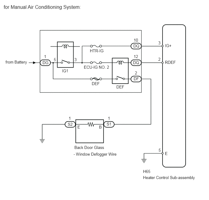
for Manual Air Conditioning System:
-
When the rear window defogger switch, which is built into the heater control, is operated, operation signals are transmitted to the DEF relay coil . When the DEF relay coil receives the signals, the DEF relay switch turns on to operate the rear window defogger.
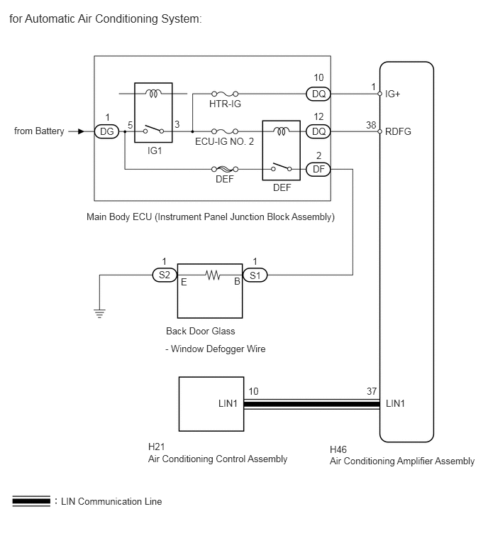
for Automatic Air Conditioning System:
-
When the rear window defogger switch is turned on, a rear window defogger activation request signal is sent via the LIN communication line to the air conditioning amplifier. Then the air conditioning amplifier operates the rear window defogger. When the on signal from the switch is received, the DEF relay is operated for 15 minutes. Also, if the off signal from the switch is received within 15 minutes, the DEF relay operation is stopped.
WIRING DIAGRAM
CAUTION / NOTICE / HINT
Inspect the fuses for circuits related to this system before performing the following inspection procedure.
PROCEDURE
READ VALUE USING INTELLIGENT TESTER (Battery Voltage Lo Record)
Using the intelligent tester, inspect battery voltage reduction history "Battery Voltage Lo Record" in the Data List.
Table 1. EMPS Tester Display
Measurement item/Range
Normal Condition
Diagnostic Note
Battery Voltage Lo Record
Battery voltage reduction history/ Min.: 0 times, Max.: 65535 times
0 to 65535
-
Table 2. Result Result
Proceed to
Other than 0 (history record is present)
A
0 (no history record is present)
B
CHECK AIR CONDITIONING SYSTEM TYPE
Check the air conditioning system type.
Table 3. Result Result
Proceed to
Automatic Air Conditioning System
A
Manual Air Conditioning System
B
CHECK HARNESS AND CONNECTOR (MAIN BODY ECU - BATTERY)Click here
CHECK FOR DTC
Check for DTCs.
Table 4. Result Result
Proceed to
DTC is not output
A
LIN DTC is output
B
PERFORM ACTIVE TEST USING INTELLIGENT TESTER (DEF RELAY)
Select the Active Test using the intelligent tester to generate a control command, and then check that the rear window defogger operates.
Table 5. Air Conditioner Tester Display
Test Part
Control Range
Diagnostic Note
Defogger Relay (Rear)
Rear window defogger relay operation
OFF/ON
-
Check that operation sound of the DEF relay is heard.
Table 6. Result Result
Proceed to
The window defogger system operates normally when operating it through the intelligent tester.
A
The window defogger system does not operate normally when operating it through the intelligent tester and DEF relay operating sound is not heard.
B
The window defogger system does not operate normally when operating it through the intelligent tester and DEF relay operating sound is heard.
C
CHECK HARNESS AND CONNECTOR (MAIN BODY ECU - BATTERY)Click here
CHECK HARNESS AND CONNECTOR (BACK DOOR GLASS - MAIN BODY ECU AND BODY GROUND)Click here
REPLACE AIR CONDITIONING CONTROL ASSEMBLY
Temporarily replace the air conditioning control assembly with a new or normally functioning one (Click here).
CHECK WINDOW DEFOGGER SYSTEM
Turn the ignition switch to ON.
Check that pressing the defogger switch illuminates the indicator and warms the rear window surface.
Check that after approximately 15 minutes, the indicator light turns off and the rear window defogger deactivates.
OK
Rear window defogger system is functioning normally.
END (AIR CONDITIONING CONTROL ASSEMBLY IS DEFECTIVE)
CHECK HARNESS AND CONNECTOR (MAIN BODY ECU - BATTERY)
-
Disconnect the DG main body ECU connector.
Measure the voltage according to the value(s) in the table below.
Standard Voltage
Tester Connection
Condition
Specified Condition
DG-1 - Body ground
Always
11 to 14 V
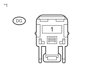
Table 7. Text in Illustration *1
Front view of wire harness connector
(to Main Body ECU)
Table 8. Result Result
Proceed to
OK (for Automatic Air Conditioning System)
A
OK (for Manual Air Conditioning System)
B
NG
C
CHECK HARNESS AND CONNECTOR (HEATER CONTROL - MAIN BODY ECU)Click here
REPAIR OR REPLACE HARNESS OR CONNECTOR
-
CHECK HARNESS AND CONNECTOR (AIR CONDITIONING AMPLIFIER - MAIN BODY ECU)
-
Disconnect the DQ main body ECU connector.
Disconnect the H46 air conditioning amplifier connector.
Measure the resistance according to the value(s) in the table below.
Standard Resistance
Tester Connection
Condition
Specified Condition
H46-38 (RDFG) - DQ-12
Always
Below 1 Ω
H46-1 (IG+) - DQ-10
H46-38 (RDFG) - Body ground
Always
10 kΩ or higher
H46-1 (IG+) - Body ground
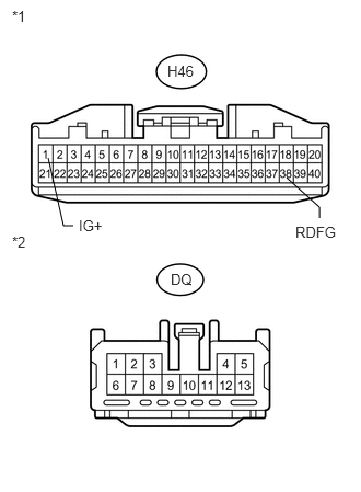
Table 9. Text in Illustration *1
Front view of wire harness connector
(to Air Conditioning Amplifier)
*2
Front view of wire harness connector
(to Main Body ECU)
REPAIR OR REPLACE HARNESS OR CONNECTOR
-
CHECK HARNESS AND CONNECTOR (AIR CONDITIONING AMPLIFIER ASSEMBLY - BATTERY)
-
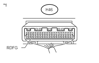
Reconnect the H46 air conditioning amplifier connector.
Measure the voltage according to the value(s) in the table below.
Standard Voltage
Tester Connection
Condition
Specified Condition
H46-38 (RDFG) - Body ground
Ignition switch ON
11 to 14 V
Table 10. Text in Illustration *1
Front view of wire harness connector
(to Air Conditioning Amplifier)
REPLACE MAIN BODY ECU (INSTRUMENT PANEL JUNCTION BLOCK ASSEMBLY)
-
CHECK HARNESS AND CONNECTOR (HEATER CONTROL - MAIN BODY ECU)
-
Disconnect the DQ main body ECU connector.
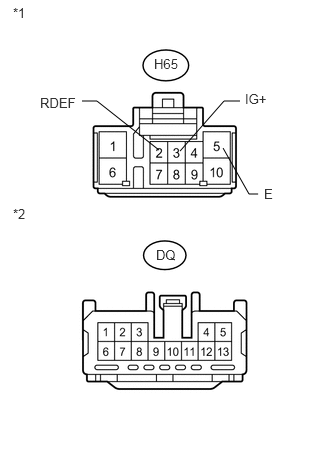
Disconnect the H65 heater control connector.
Measure the resistance according to the value(s) in the table below.
Standard Resistance
Tester Connection
Condition
Specified Condition
H65-2 (RDEF) - DQ-12
Always
Below 1 Ω
H65-3 (IG+) - DQ-10
H65-5 (E) - Body ground
H65-2 (RDEF) - Body ground
Always
10 kΩ or higher
H65-3 (IG+) - Body ground
Table 11. Text in Illustration *1
Front view of wire harness connector
(to Heater Control)
*2
Front view of wire harness connector
(to Main Body ECU)
REPAIR OR REPLACE HARNESS OR CONNECTOR
-
CHECK HARNESS AND CONNECTOR (HEATER CONTROL - BATTERY AND BODY GROUND)
-
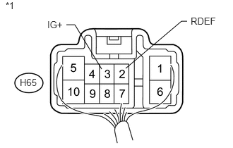
Reconnect the H65 heater control connector.
Measure the voltage according to the value(s) in the table below.
Standard Voltage
Tester Connection
Condition
Specified Condition
H65-2 (RDEF) - Body ground
Ignition switch ON
11 to 14 V
H65-3 (IG+) - Body ground
Table 12. Text in Illustration *1
Front view of wire harness connector
(to Heater Control)
-
CHECK HARNESS AND CONNECTOR (BACK DOOR GLASS - MAIN BODY ECU AND BODY GROUND)
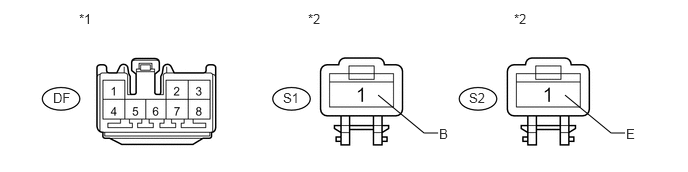
Disconnect the DF main body ECU connector.
Disconnect the S1 and S2 rear window defogger wire connectors.
Measure the resistance according to the value(s) in the table below.
Standard Resistance
Tester Connection
Condition
Specified Condition
S1-1 (B) - DF-2
Always
Below 1 Ω
S2-1 (E) - Body ground
S1-1 (B) - Body ground
Always
10 kΩ or higher
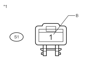
Table 13. Text in Illustration *1
Front view of wire harness connector
(to Main Body ECU)
*2
Front view of wire harness connector
(to Back Door Glass)
REPAIR OR REPLACE HARNESS OR CONNECTOR
CHECK HARNESS AND CONNECTOR (WINDOW DEFOGGER WIRE)
-
Measure the voltage according to the value(s) in the table below.
Standard Voltage
Tester Connection
Switch Condition
Specified Condition
S1-1 (B) - Body ground
Ignition switch ON and defogger switch on
11 to 14 V
Table 14. Text in Illustration *1
Front view of wire harness connector
(to Back Door Glass)
REPLACE MAIN BODY ECU (INSTRUMENT PANEL JUNCTION BLOCK ASSEMBLY)
-