FUEL SUPPLY PUMP (for DPF) REMOVAL
Note
-
When replacing the injectors (including shuffling the injectors between the cylinders), common rail or cylinder head, it is necessary to replace the injection pipes with new ones.
-
When replacing the fuel supply pump, common rail, cylinder block, cylinder head, cylinder head gasket or timing gear case, it is necessary to replace the fuel inlet pipe with a new one.
-
After removing the fuel inlet pipe, clean it with a brush and compressed air.
-
DISCONNECT CABLE FROM NEGATIVE BATTERY TERMINAL
Note
When disconnecting the cable, some systems need to be initialized after the cable is reconnected Click here.
-
REMOVE RADIATOR ASSEMBLY
-
REMOVE TIMING BELT
-
REMOVE ELECTRIC EGR CONTROL VALVE ASSEMBLY WITH NO. 2 EGR VALVE AND EGR COOLER
-
REMOVE NO. 4 INJECTION PIPE SUB-ASSEMBLY
-
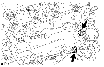
Remove the bolt, nut and 2 No. 2 injection pipe clamps.
-
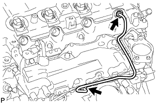
Using a 17 mm union nut wrench, loosen the union nuts and remove the No. 4 injection pipe.
-
-
REMOVE WIRING HARNESS CLAMP BRACKET
-
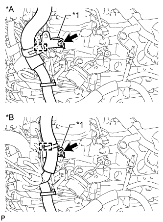
Text in Illustration *A for LHD *B for RHD *1 Wiring Harness Clamp Bracket Detach the wire harness clamp.
-
Remove the bolt and wiring harness clamp bracket.
-
-
REMOVE NO. 2 FUEL PIPE
-
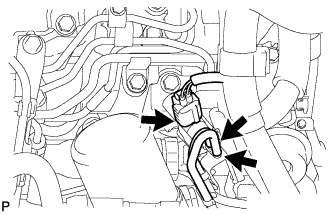
Disconnect the vacuum switching valve connector and 2 vacuum transmitting hoses.
-
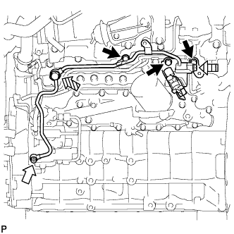
Using a 6 mm hexagon wrench, remove the supply pump hollow screw and gasket.
Text in Illustration 
Bolt 
Supply Pump Hollow Screw 
Fuel Check Valve 
Union Bolt -
Remove the fuel check valve, union bolt and 2 gaskets.
-
Remove the 3 bolts and No. 2 fuel pipe.
-
-
REMOVE FUEL SUPPLY PUMP ASSEMBLY
-
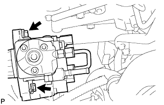
Disconnect the 2 fuel hoses.
-
Disconnect the fuel temperature sensor connector and suction control valve connector from the fuel supply pump.
-
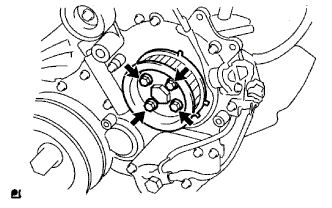
Remove the 4 bolts indicated by the arrows in the illustration.
-
Remove the No. 2 camshaft timing pulley flange and pump drive shaft pulley.
-
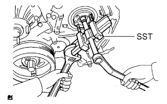
Remove the set nut and O-ring while holding the crankshaft pulley using SST.
- SST
- 09213-58014
- 09330-00021
-
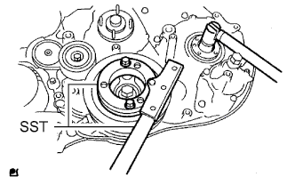
Loosen the 2 nuts.
-
Using SST, disconnect the fuel supply pump from the injection gear.
- SST
- 09950-50013 ( 09951-05010, 09952-05010, 09953-05020, 09954-05021 )
Note
Apply lubricant to the threads and tip of SST (center bolt) before using it.
-
Remove the 2 nuts and fuel supply pump.
Note
-
Do not hold or carry the fuel supply pump by the pipe.
-
The fuel supply pump must be kept horizontal.
-
-
Remove the O-ring.
-