CONDENSER REMOVAL
CAUTION / NOTICE / HINT
The necessary procedures (adjustment, calibration, initialization, or registration) that must be performed after parts are removed, installed, or replaced during the condenser removal/installation are shown below.
| Replacement Part or Procedure | Necessary Procedures | Effects / Inoperative when not performed | Link |
|---|---|---|---|
| Disconnect cable from negative battery terminal | Memorize steering angle neutral point | Lane departure alert system (w/ Steering Control) | |
| Simple intelligent parking assist system*1 | |||
| Toyota parking assist-sensor system (w/ Simple Intelligent Parking Assist System)*1 | |||
| Pre-collision system | |||
| Initialize back door lock | Power door lock control system | ||
| Drive the vehicle until stop and start control is permitted (approximately 5 to 60 minutes)*2 | Stop and start system |
*1: When performing learning using the GTS.
*2: w/ Stop and start system
PROCEDURE
-
RECOVER REFRIGERANT FROM REFRIGERATION SYSTEM (for HFC-134a(R134a))
-
RECOVER REFRIGERANT FROM REFRIGERATION SYSTEM (for HFO-1234yf(R1234yf))
-
REMOVE HEADLIGHT ASSEMBLY LH (for Halogen Headlight)
-
REMOVE HEADLIGHT ASSEMBLY LH (for LED Headlight)
-
REMOVE HEADLIGHT ASSEMBLY RH (for Halogen Headlight)
Tech Tips
Use the same procedure as for the LH side.
-
REMOVE HEADLIGHT ASSEMBLY RH (for LED Headlight)
Tech Tips
Use the same procedure as for the LH side.
-
REMOVE NO. 1 AIR CLEANER INLET (for 8NR-FTS)
-
REMOVE NO. 1 AIR CLEANER INLET (for 3ZR-FAE)
-
REMOVE FRONT BUMPER UPPER REINFORCEMENT SUB-ASSEMBLY (for 8NR-FTS)
-
REMOVE FRONT BUMPER UPPER REINFORCEMENT SUB-ASSEMBLY (for 3ZR-FAE)
-
REMOVE NO. 1 RADIATOR GRILLE RETAINER
-
REMOVE NO. 1 RADIATOR TO SUPPORT SEAL
-
REMOVE HOOD LOCK NUT CAP
-
REMOVE HOOD LOCK ASSEMBLY
-
w/ Engine Hood Courtesy Switch:
-
w/o Engine Hood Courtesy Switch:
-
-
REMOVE UPPER RADIATOR SUPPORT SUB-ASSEMBLY (for 8NR-FTS)
-
REMOVE UPPER RADIATOR SUPPORT SUB-ASSEMBLY (for 3ZR-FAE)
-
REMOVE NO. 2 RADIATOR AIR GUIDE (for 8NR-FTS)
-
REMOVE NO. 2 RADIATOR AIR GUIDE (for 3ZR-FAE)
-
REMOVE FRONT BUMPER ENERGY ABSORBER
-
REMOVE FRONT BUMPER REINFORCEMENT
-
REMOVE NO. 1 RADIATOR AIR GUIDE LH
-
REMOVE NO. 1 RADIATOR AIR GUIDE RH
-
DISCONNECT DISCHARGE HOSE SUB-ASSEMBLY
-
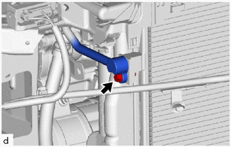
Remove the bolt to disconnect the discharge hose sub-assembly from the cooler condenser assembly.
-
Remove the O-ring from the discharge hose sub-assembly.
Note
Seal the openings of the disconnected parts using vinyl tape to prevent entry of moisture and foreign matter.
-
-
DISCONNECT COOLER REFRIGERANT LIQUID PIPE A (for VALEO Made)
-
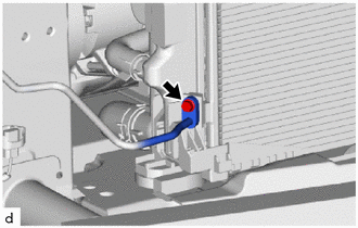
Remove the bolt to disconnect the cooler refrigerant liquid pipe A from the cooler condenser assembly.
-
Remove the O-ring from the cooler refrigerant liquid pipe A.
Note
Seal the openings of the disconnected parts using vinyl tape to prevent entry of moisture and foreign matter.
-
-
DISCONNECT COOLER REFRIGERANT LIQUID PIPE A (for DENSO Made)
-
While pressing the end of the suction pipe sub-assembly into the end of the cooler condenser assembly, use pliers to squeeze together both sides of the piping clamp until it breaks apart.
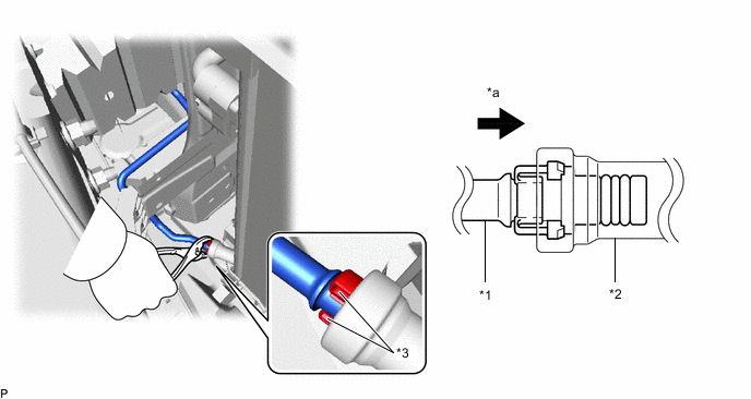
*1 Suction Pipe Sub-assembly *2 Cooler Condenser Assembly *3 Piping Clamp - - *a Press In - - Note
-
If any foreign matter is adhered to the connecting part, brush it off or use compressed air to remove it.
-
Make sure that fragments of the piping clamp do not enter the piping.
-
-
Disconnect the suction pipe sub-assembly.
Note
Clean off any foreign matter near the ends of the suction pipe sub-assembly and cooler condenser assembly.
-
Remove the 2 O-rings from the suction pipe sub-assembly.
Note
Wrap the open ends of the separated cooler condenser assembly and suction pipe sub-assembly accessory assembly with vinyl tape to prevent entry of moisture and foreign matter.
-
Remove the piping clamp.
-
-
REMOVE COOLER CONDENSER ASSEMBLY
-
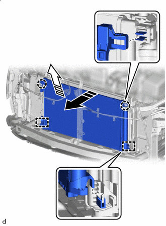

Remove in this Direction Disengage the claws and guides to remove the cooler condenser assembly as shown in the illustration.
Note
Do not damage the cooler condenser assembly or radiator assembly when removing the cooler condenser assembly.
-