SFI SYSTEM
-
CONSTRUCTION
-
The basic components of the continuously variable valve lift controller assembly are an EDU, a brushless motor and a differential roller converter.
-
The internal gears of the continuously variable valve lift controller assembly are lubricated by engine oil.
-
A neodymium magnet is used in a flat, brushless motor to achieve a compact size. The flat, brushless motor is a DC motor from which the brushes and the commutator have been eliminated. A multipolar magnetized magnet acts as a rotor, which switches the polarity of the voltage applied to the surrounding stator actuation coil in sync with the rotation of the rotor. The resulting alternating field and the rotor magnet magnaflux cause attraction and repulsion to generate torque.
Tech Tips
Neodymium magnet: A neodymium magnet is a type of rare earth magnet composed primarily of neodymium, iron and boron. The neodymium magnet has a high magnaflux density to provide an extremely strong magnetism.
-
The EDU operates the motor in accordance with signals from the ECM. The differential roller converter converts the rotational movement of the motor into a linear movement. This linear movement operates the VALVEMATIC mechanism.
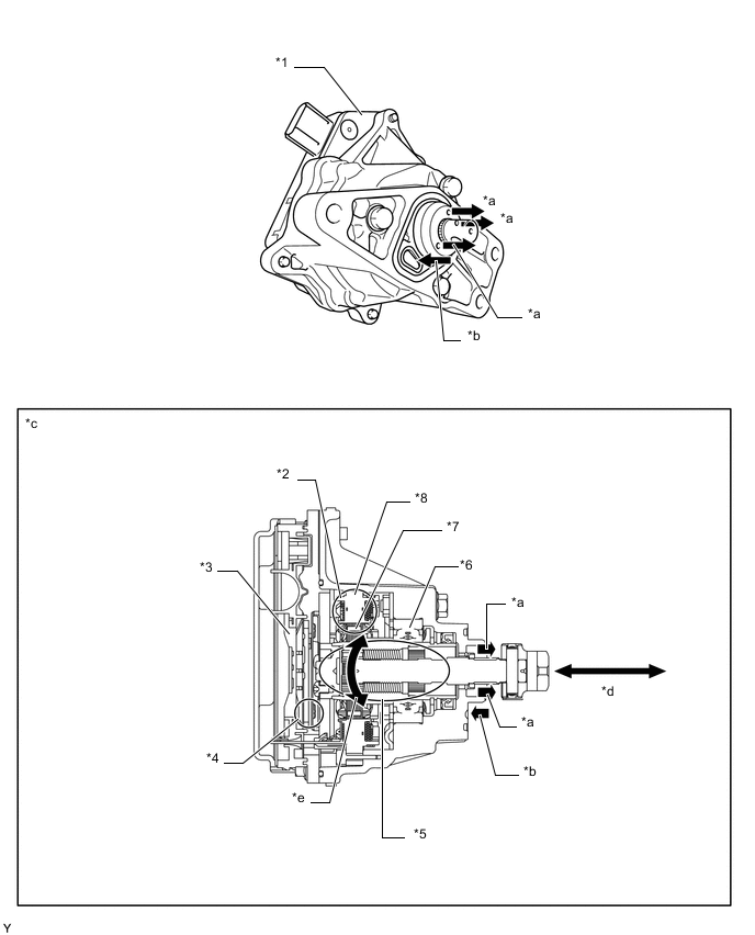
*1 Continuously Variable Valve Lift Controller Assembly *2 Motor Portion *3 EDU *4 Sensor Portion
-
Motor Position Sensor
-
Action Angle Sensor
*5 Differential Roller Converter *6 Bearing *7 Rotor/Motor *8 Stator *a Engine Oil Out *b Engine Oil In *c Continuously Variable Valve Lift Controller Assembly Cross Section *d Linear Movement *e Rotational Movement - - -
-
The motor rotates the nut on the differential roller converter. The movement of the nut travels to the planetary unit (gear) and the planetary unit (screw) and causes the sun shaft to move linearly.
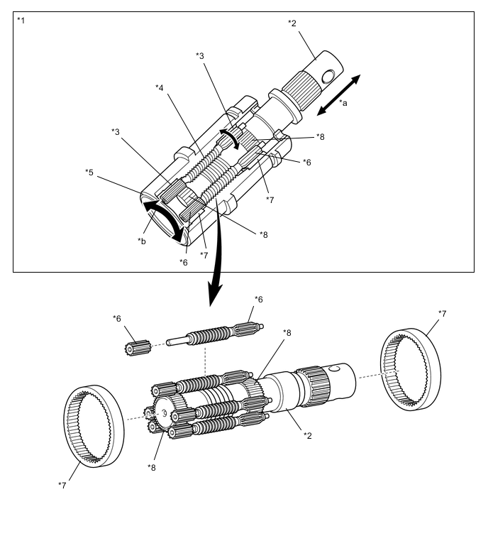
*1 Differential Roller Converter *2 Sun Shaft *3 Planetary Unit (Gear) *4 Planetary Unit (Screw) *5 Nut *6 Pinion *7 Ring Gear *8 Sun Gear *a Linear Movement *b Rotational Movement
-
-
OPERATION
-
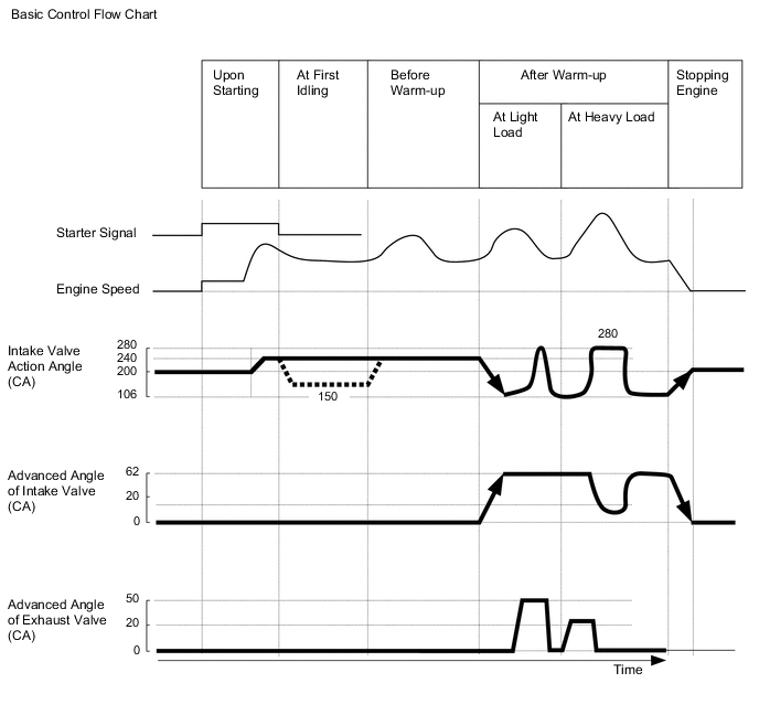
On the basic control, the ECM determines the target intake air volume in accordance with the accelerator pedal depressed angle, engine speed and various sensor signals. The EDU, which is integrated into the continuously variable valve lift controller assembly, determines the target amount of lift and the action angle of the intake valve in accordance with signals from the ECM.
-
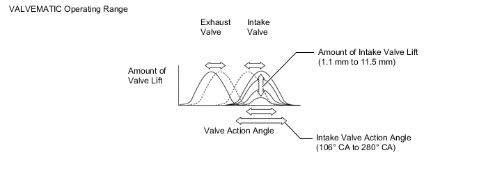
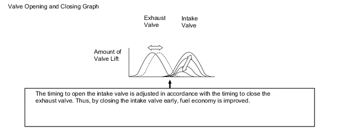
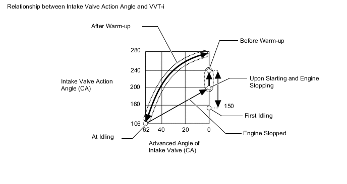
To optimize the valve opening and closing timing, the VALVEMATIC effects coordinate control with the Dual VVT-i. Thus, the VALVEMATIC controls the amount of valve lift and the action angle in accordance with the driving conditions. Because the VALVEMATIC features timing advance characteristics in which the amount of valve lift and the action angle vary, it effects the proper control to attain the intended amount of valve lift. This VVT-i has timing advance characteristics that differ from the conventional Dual VVT-i control.
-
The following table shows the coordinate control of the VALVEMATIC with ETCS-i during basic control:
Control Operation Starting Control VALVEMATIC controls the intake valve action angle, and ETCS-i operates the throttle valve to control the intake air volume. First Idle Control Before Warm-up Control After Warm-up Control
-
VALVEMATIC controls the amount of intake valve lift and the intake valve timing, and ETCS-i opens the throttle valve wider than the normal opening and reduces the intake manifold negative pressure in order to minimize pumping loss.
-
During idling, when the intake air volume is small, the ETCS-i controls the intake air volume as in the past.
Engine Stop Control -
-