FRONT SUSPENSION MEMBER REMOVAL
PROCEDURE
ALIGN FRONT WHEELS FACING STRAIGHT AHEAD
SECURE STEERING WHEEL
REMOVE STEERING COLUMN HOLE COVER PLATE
SEPARATE NO. 2 STEERING INTERMEDIATE SHAFT ASSEMBLY
SEPARATE NO. 1 STEERING COLUMN HOLE COVER SUB-ASSEMBLY
REMOVE FRONT WHEELS
REMOVE EXHAUST PIPE ASSEMBLY
SEPARATE TIE ROD END SUB-ASSEMBLY LH
SEPARATE TIE ROD END SUB-ASSEMBLY RH
Tip:Perform the same procedure as for the LH side.
REMOVE FRONT STABILIZER BOLT (for LH Side)
REMOVE FRONT STABILIZER BOLT (for RH Side)
Tip:Perform the same procedure as for the LH side.
SEPARATE FRONT LOWER NO. 1 SUSPENSION ARM SUB-ASSEMBLY LH
SEPARATE FRONT LOWER NO. 1 SUSPENSION ARM SUB-ASSEMBLY RH
Tip:Perform the same procedure as for the LH side.
REMOVE FRONT SUSPENSION CROSSMEMBER SUB-ASSEMBLY
-
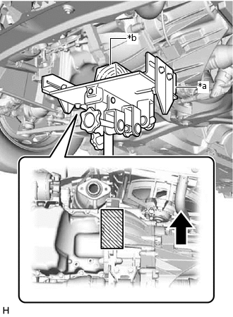
*a
Jack
*b
Wooden Block

Front of the Vehicle

Wooden Block Placement Location
Using a jack and a wooden block, support the engine and transaxle assembly.
-
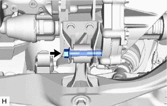
Remove the bolt and separate the engine moving control rod.
-
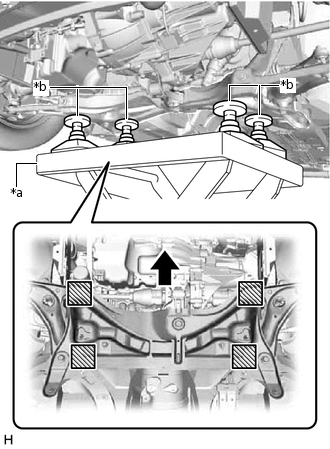
*a
Engine Lifter
*b
Attachment
Front of the Vehicle
Attachment Placement Location
Support the front suspension crossmember sub-assembly with an engine lifter using 4 attachments or equivalent tools as shown in the illustration.
CAUTION:The front suspension crossmember sub-assembly is a heavy component. Make sure that it is supported securely.
Make sure to secure the front suspension crossmember sub-assembly to prevent it from dropping.
Note:Use the attachments to keep the front suspension crossmember sub-assembly level.
Remove the 6 bolts and front suspension crossmember sub-assembly.
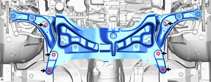
Slowly lower the front suspension crossmember sub-assembly.
Note:When lowering the front suspension crossmember sub-assembly, be careful not to damage the vehicle body or other components installed to the vehicle.
-
REMOVE STEERING LINK ASSEMBLY
REMOVE FRONT STABILIZER BAR
REMOVE FRONT LOWER NO. 1 SUSPENSION ARM SUB-ASSEMBLY LH
-
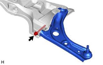
Remove the bolt and front lower No. 1 suspension arm sub-assembly LH from the front suspension crossmember sub-assembly.
-
REMOVE FRONT LOWER NO. 1 SUSPENSION ARM SUB-ASSEMBLY RH
Tip:Perform the same procedure as for the LH side.
REMOVE ENGINE MOVING CONTROL ROD
-
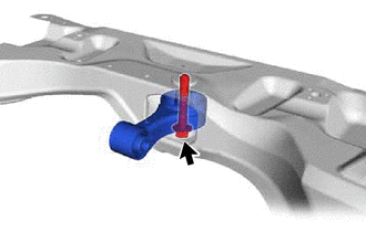
Remove the bolt and engine moving control rod from the front suspension crossmember sub-assembly.
-
REMOVE FRONT SUSPENSION MEMBER DYNAMIC DAMPER (w/ Dynamic Damper)
-
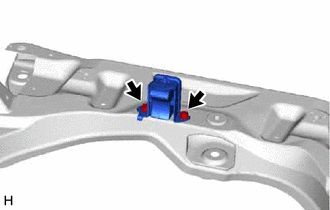
Remove the 2 bolts and front suspension member dynamic damper from the front suspension crossmember sub-assembly.
-