AIR CONDITIONING SYSTEM Air Conditioning Compressor Magnetic Clutch Circuit
DESCRIPTION
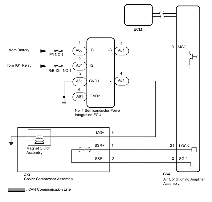
When the air conditioning amplifier assembly is turned ON, a magnet clutch on signal is sent from the MGC terminal of the air conditioning amplifier assembly. Then, the No. 1 semiconductor power integration ECU turns on to operate the magnet clutch assembly.
WIRING DIAGRAM
CAUTION / NOTICE / HINT
Note
-
The air conditioning system uses the CAN communication system and CXPI system. First, confirm that there is no malfunction in the CAN communication system and CXPI system. Refer to the How to Proceed with Troubleshooting procedure.
-
ECM malfunctions can affect the storage of this DTC. Therefore, check all SFI system DTCs and confirm that the system is normal before performing the following inspection.
-
Inspect the fuses for circuits related to this system before performing the following procedure.
PROCEDURE
-
CHECK CAN COMMUNICATION SYSTEM
-
Using the GTS, check if the CAN communication system is functioning normally.
OK CAN communication system DTCs are not output. Result Proceed to OK NG
NG 
GO TO CAN COMMUNICATION SYSTEM Click here
OK 
-
-
CHECK CXPI COMMUNICATION SYSTEM
-
Using the GTS, check if the CXPI communication system is functioning normally.
OK CXPI communication system DTCs are not output. Result Proceed to OK NG
NG
GO TO CXPI COMMUNICATION SYSTEM Click here
OK
-
-
CHECK POWER INTEGRATION SYSTEM
-
Using the GTS, check if the power integration system is functioning normally.
OK Power integration system DTCs are not output. Result Proceed to OK NG
NG
GO TO POWER INTEGRATION SYSTEM Click here
OK
-
-
CHECK COOLER COMPRESSOR ASSEMBLY
-
Disconnect the D72 cooler compressor assembly connector.
-
Connect the GTS to the DLC3.
-
Turn the engine switch on (IG).
-
Turn the GTS on.
-
Enter the following menus: Body Electrical / Air Conditioner / Active Test.
-
Check the operation by referring to the table below.
Body Electrical > Air Conditioner > Active TestTester Display Measurement Item Control Range Diagnostic Note Magnetic Clutch Relay Air conditioning system operation OFF/ON Perform this test when the following conditions are met:
-
Engine switch on (IG)
-
Air conditioning system is operated
Body Electrical > Air Conditioner > Active TestTester Display Magnetic Clutch Relay -
-
Measure the voltage according to the value(s) in the table below.
Standard Voltage Tester Connection Switch Condition Specified Condition A61-4 (L) - Body ground Perform Active Test and select "OFF" 11 to 14 V Perform Active Test and select "ON" Below 1 V Result Proceed to OK NG
NG 
CHECK HARNESS AND CONNECTOR (AIR CONDITIONING AMPLIFIER ASSEMBLY - NO. 1 SEMICONDUCTOR POWER INTEGRATION ECU) Click here
OK
-
-
READ VALUE USING GTS (STATUS OF A/C MAGNETIC CLUTCH FUSE)
-
Connect the GTS to the DLC3.
-
Turn the engine switch on (IG).
-
Turn the GTS on.
-
Enter the following menus: Body Electrical / Power Integration No.1 / Data List.
-
Read the Data List according to the display on the GTS.
Body Electrical > Power Integration No.1 > Data ListTester Display Measurement Item Range Normal Condition Diagnostic Note Status of A/C Magnetic Clutch Fuse Cooler compressor assembly fuse Connect or Disconnect Connect: Fuse not shut off
Disconnect: Fuse shut off
-
Body Electrical > Power Integration No.1 > Data ListTester Display Status of A/C Magnetic Clutch Fuse OK The Data List value displays "Connect". Result Proceed to OK NG
NG
CHECK COOLER COMPRESSOR ASSEMBLY Click here
OK
-
-
READ VALUE USING GTS (A/C MAGNETIC CLUTCH INPUT SIGNAL)
-
Connect the GTS to the DLC3.
-
Turn the engine switch on (IG).
-
Turn the GTS on.
-
Enter the following menus: Body Electrical / Power Integration No.1 / Data List.
-
Read the Data List according to the display on the GTS.
Body Electrical > Power Integration No.1 > Data ListTester Display Measurement Item Range Normal Condition Diagnostic Note A/C Magnetic Clutch Input Signal Cooler Compressor assembly input status OFF or ON OFF: Cooler compressor assembly does not operate
ON: Cooler compressor assembly operates
-
Body Electrical > Power Integration No.1 > Data ListTester Display A/C Magnetic Clutch Input Signal OK Display changes according to heater accessory operation. Result Proceed to OK NG
NG
REPLACE MAIN BODY ECU (MULTIPLEX NETWORK BODY ECU) Click here
OK
-
-
READ VALUE USING GTS (A/C MAGNETIC CLUTCH OUTPUT SIGNAL)
-
Connect the GTS to the DLC3.
-
Turn the engine switch on (IG).
-
Turn the GTS on.
-
Enter the following menus: Body Electrical / Power Integration No.1 / Data List.
-
Read the Data List according to the display on the GTS.
Body Electrical > Power Integration No.1 > Data ListTester Display Measurement Item Range Normal Condition Diagnostic Note A/C Magnetic Clutch Output Signal Cooler compressor assembly output status OFF or ON OFF: Cooler compressor assembly does not operate
ON: Cooler compressor assembly operates
-
Body Electrical > Power Integration No.1 > Data ListTester Display A/C Magnetic Clutch Output Signal OK Display changes according to Cooler compressor operation. Result Proceed to OK NG
NG
REPLACE NO. 1 SEMICONDUCTOR POWER INTEGRATION ECU Click here
OK
-
-
INSPECT COOLER COMPRESSOR ASSEMBLY
-
Remove the cooler compressor assembly.
-
Inspect the cooler compressor assembly.
Result Proceed to OK NG
NG
REPLACE COOLER COMPRESSOR ASSEMBLY Click here
OK
-
-
CHECK HARNESS AND CONNECTOR (COOLER COMPRESSOR ASSEMBLY - NO. 1 SEMICONDUCTOR POWER INTEGRATION ECU)
-
Disconnect the D72 cooler compressor assembly connector.
-
Disconnect the A61 No. 1 semiconductor power integration ECU connector.
-
Measure the resistance according to the value(s) in the table below.
Standard Resistance Tester Connection Condition Specified Condition D72-3 (MG+) - A61-4 (L) Always Below 1 Ω D72-3 (MG+) or A61-4 (L) - Other terminals and body ground Always 10 kΩ or higher Result Proceed to OK NG
OK
REPLACE NO. 1 SEMICONDUCTOR POWER INTEGRATION ECU Click here
NG
REPAIR OR REPLACE HARNESS OR CONNECTOR
-
-
CHECK COOLER COMPRESSOR ASSEMBLY
-
Disconnect the D72 cooler compressor assembly connector.
-
Connect the GTS to the DLC3.
-
Turn the engine switch on (IG).
-
Turn the GTS on.
-
Enter the following menus: Body Electrical / Power Integration No.1 / Data List.
-
Read the Data List according to the display on the GTS.
Body Electrical > Power Integration No.1 > Data ListTester Display Measurement Item Range Normal Condition Diagnostic Note Status of A/C Magnetic Clutch Fuse Cooler compressor assembly fuse Connect or Disconnect Connect: Fuse not shut off
Disconnect: Fuse shut off
-
Body Electrical > Power Integration No.1 > Data ListTester Display Status of A/C Magnetic Clutch Fuse OK The Data List value displays "Connect". Result Proceed to OK NG
OK
GO TO STEP 9 Click here
NG
REPLACE COOLER COMPRESSOR ASSEMBLY Click here
-
-
CHECK HARNESS AND CONNECTOR (AIR CONDITIONING AMPLIFIER ASSEMBLY - NO. 1 SEMICONDUCTOR POWER INTEGRATION ECU)
-
Disconnect the G64 air conditioning amplifier assembly connector.
-
Disconnect the A61 No. 1 semiconductor power integration ECU connector.
-
Measure the resistance according to the value(s) in the table below.
Standard Resistance Tester Connection Condition Specified Condition G64-9 (MGC) - A61-5 (-S) Always Below 1 Ω G64-9 (MGC) or A61-5 (-S) - Other terminals and body ground Always 10 kΩ or higher Result Proceed to OK NG
OK
REPLACE AIR CONDITIONING AMPLIFIER ASSEMBLY Click here
NG
REPAIR OR REPLACE HARNESS OR CONNECTOR
-