PRE-COLLISION SYSTEM, Diagnostic DTC:C1A4B
| DTC Code | DTC Name |
|---|---|
| C1A4B | Stop Light Relay Circuit |
DESCRIPTION
The skid control ECU (brake actuator assembly) sends a stop light operation request signal to the stop light switch assembly. If the skid control ECU (brake actuator assembly) detects a malfunction in the stop light switch assembly circuit, the millimeter wave radar sensor assembly stores DTC C1A4B.
| DTC No. | Detection Item | DTC Detection Condition | Trouble Area |
|---|---|---|---|
| C1A4B | Stop Light Relay Circuit | Diagnosis condition:
Malfunction condition: Either of the following conditions is met:
|
|
| Vehicle Condition | |||
|---|---|---|---|
| Pattern 1 | Pattern 2 | ||
| Diagnosis Condition | Ignition switch to ON and battery voltage between 11 and 14 V. | ○ | ○ |
| Malfunction Status | When the stop light illumination output (STPO) signal is on, a signal has not been input to the STP2 terminal. | ○ | - |
| When the stop light illumination output (STPO) signal is off, signals input to the STP terminal and STP2 terminal of the skid control ECU (brake actuator assembly). | - | ○ | |
| Detection Time | 0.3 seconds | 0.3 seconds | |
| Number of Trips | 1 trip | 1 trip | |
Tech Tips
DTC will be output when conditions for either of the patterns in the table above are met.
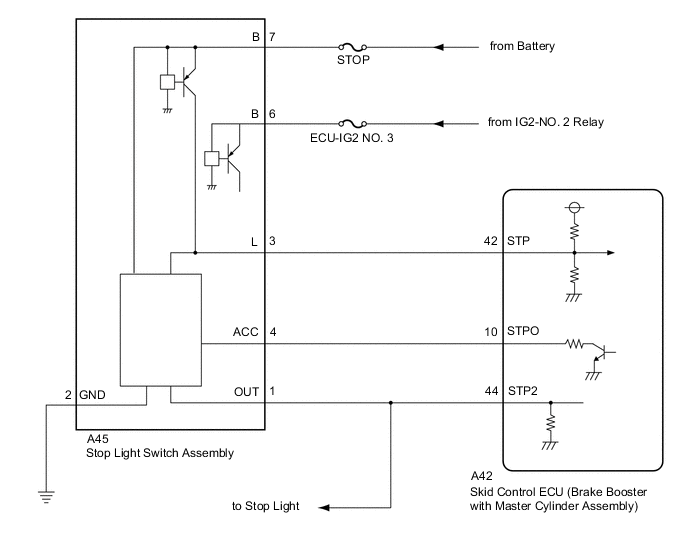
WIRING DIAGRAM
CAUTION / NOTICE / HINT
Note
The pre-collision system uses the CAN communication system. First, confirm that there are no malfunction in the CAN communication system. Refer to How to Proceed with Troubleshooting.
PROCEDURE
-
CHECK FOR DTCs (VEHICLE STABILITY CONTROL SYSTEM)
Tech Tips
Pre-collision system DTC C1A4B may be stored due to a malfunction in the VSC system. Therefore, it is necessary to check for and troubleshoot VSC system DTCs first.
-
Check for DTCs.
Chassis > ABS/VSC/TRC/EPB > Trouble CodesResult Result Proceed to Vehicle stability control system DTCs are not output A Vehicle stability control system DTCs are output B
B 
GO TO VEHICLE STABILITY CONTROL SYSTEM Click here
A 
-
-
CHECK FOR DTCs (PRE-COLLISION SYSTEM)
-
Clear the DTCs.
Body Electrical > Pre-Collision 2 > Clear DTCs -
Make sure that the DTC detection conditions are met.
Tech Tips
If the detection conditions are not met, the system cannot detect the malfunction.
-
Check for DTCs.
Body Electrical > Pre-Collision 2 > Trouble CodesResult Result Proceed to DTC C1A4B is output A DTC C1A4B is not output B
B
USE SIMULATION METHOD TO CHECK Click here
A
-
-
REPLACE MILLIMETER WAVE RADAR SENSOR ASSEMBLY
-
Replace the millimeter wave radar sensor assembly.
-
Adjust the millimeter wave radar sensor assembly.
Result Proceed to NEXT
NEXT
-
-
CHECK FOR DTCs (PRE-COLLISION SYSTEM)
Tech Tips
After performing the radar sensor beam axis adjustment, if the same DTC is output again after the DTC detection conditions are met, replace the millimeter wave radar sensor assembly.
-
Clear the DTCs.
Body Electrical > Pre-Collision 2 > Clear DTCs -
Make sure that the DTC detection conditions are met.
Tech Tips
If the detection conditions are not met, the system cannot detect the malfunction.
-
Check for DTCs.
Body Electrical > Pre-Collision 2 > Trouble CodesResult Result Proceed to DTC C1A4B is not output A DTC C1A4B is output (for LHD) B DTC C1A4B is output (for RHD) C
A
END (MILLIMETER WAVE RADAR SENSOR ASSEMBLY WAS DEFECTIVE)
B
REPLACE SKID CONTROL ECU (BRAKE ACTUATOR ASSEMBLY) Click here
C
REPLACE SKID CONTROL ECU (BRAKE ACTUATOR ASSEMBLY) Click here
-