CAN COMMUNICATION SYSTEM(for LHD), Diagnostic DTC:U1002
| DTC Code | DTC Name |
|---|---|
| U1002 | Lost Communication with Gateway Module (Main Body) |
DESCRIPTION
-
The main body ECU (multiplex network body ECU) stores this DTC when no signals can be received from the ECUs that have been memorized as those connected to the sub bus 1.
-
When the main body ECU (multiplex network body ECU) receives a response signal from the ECUs connected to the sub bus 1, the main body ECU (multiplex network body ECU) recognizes and memorizes that the ECU is connected to the sub bus 1. Based on this memorized data, the main body ECU (multiplex network body ECU) monitors for malfunctions in the ECUs connected to the sub bus 1 when communicating with those ECUs. If the main body ECU (multiplex network body ECU) cannot receive response signals from the ECUs that have been memorized as those connected to the sub bus 1, the main body ECU (multiplex network body ECU) determines that a malfunction exists.
-
If 2 or more DTCs are output during the DTC check, one side of the CAN branch wire may be open (one side of the CANH [CAN branch wire]/CANL [CAN branch wire] of the ECU and/or sensor is open).
| DTC No. | Detection Item | DTC Detection Condition | Trouble Area | DTC Output from |
|---|---|---|---|---|
| U1002 | Lost Communication with Gateway Module (Main Body) | Lost communication with the gateway module. |
|
Main body ECU (multiplex network body ECU) |
-
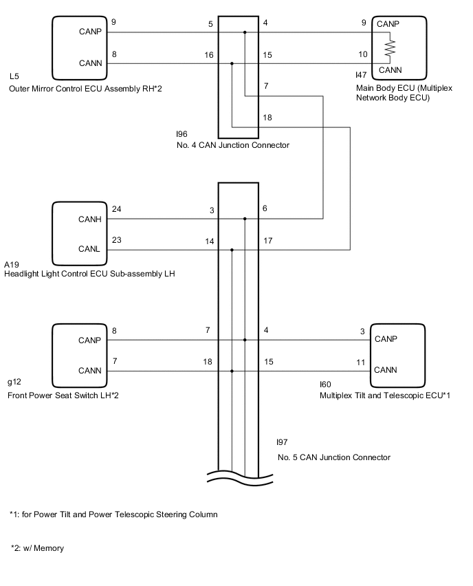
*1: for Power Tilt and Power Telescopic Steering Column
-
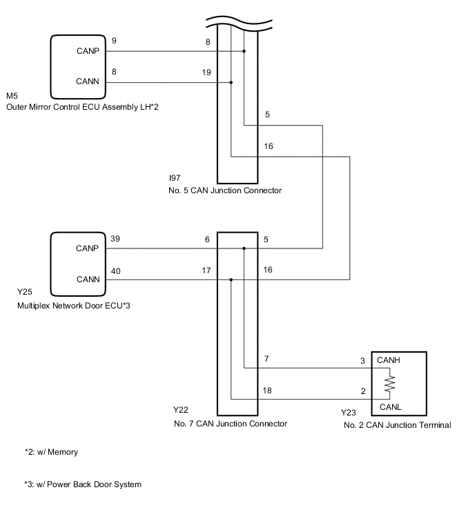
*2: w/ Memory
-
*3: w/ Power Back Door System
CAUTION / NOTICE / HINT
Note
-
Because the order of diagnosis is important to allow correct diagnosis, make sure to begin troubleshooting using How to Proceed with Troubleshooting when CAN communication system related DTCs are output.
-
Before measuring the resistance of the CAN bus, turn the engine switch off and leave the vehicle for 1 minute or more without operating the key, switches or opening or closing the doors. After that, disconnect the cable from the negative (-) battery terminal and leave the vehicle for 1 minute or more before measuring the resistance.
-
After turning the engine switch off, waiting time may be required before disconnecting the cable from the battery terminal. Therefore, make sure to read the disconnecting the cable from the battery terminal notice before proceeding with work.
-
DTC check procedure: Turn the engine switch on (IG) and wait at least 20 seconds.
-
After the repair, perform CAN Bus Check and check that all the ECUs and sensors connected to the CAN communication system are displayed.
-
If the main body ECU (multiplex network body ECU) is replaced, refer to the service bulletin.
-
As the door control battery is installed between the vehicle battery and main body ECU (multiplex network body ECU), first perform the inspections in On-Vehicle Inspection to confirm that there are no malfunctions in the power source circuit for the main body ECU (multiplex network body ECU) before performing this troubleshooting procedure.*
*: w/ Door Control Battery
Tech Tips
Even after DTCs are cleared, if a DTC is stored again after driving the vehicle for a while, the malfunction may be occurring due to vibration of the vehicle. In such a case, wiggling the ECUs or wire harness while performing the inspection below may help determine the cause of the malfunction.
PROCEDURE
-
CHECK SUB BUS 1
-

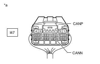
*a Component with harness connected
(to Main Body ECU [Multiplex Network Body ECU])
*b Front view of DLC3 Disconnect the cable from the negative (-) battery terminal.
-
Measure the resistance according to the value(s) in the table below.
Standard Resistance Tester Connection Condition Specified Condition Resistance: Malfunction I47-9 (CANP) - I47-10 (CANN) Cable disconnected from negative (-) battery terminal 54 to 69 Ω Below 53 Ω: Short in CAN bus wire I47-9 (CANP) - I47-10 (CANN) Cable disconnected from negative (-) battery terminal 54 to 69 Ω Higher than 70 Ω: Open in CAN main wire I47-9 (CANP) - I7-16 (BAT) Cable disconnected from negative (-) battery terminal 6 kΩ or higher Below 6 kΩ: +B short I47-10 (CANN) - I7-16 (BAT) Cable disconnected from negative (-) battery terminal 6 kΩ or higher Below 6 kΩ: +B short I47-9 (CANP) - I7-4 (CG) Cable disconnected from negative (-) battery terminal 200 Ω or higher Below 200 Ω: Ground short I47-10 (CANN) - I7-4 (CG) Cable disconnected from negative (-) battery terminal 200 Ω or higher Below 200 Ω: Ground short Result Result Proceed to OK A NG
- Open in CAN main wire
B NG
- Short in CAN bus wire
C NG
- +B short
- Ground short
D
B 
CHECK FOR OPEN IN CAN BUS MAIN WIRE (NO. 5 CAN JUNCTION CONNECTOR) Click here
C
CHECK FOR SHORT IN CAN BUS WIRES (NO. 7 CAN JUNCTION CONNECTOR) Click here
D
CHECK FOR SHORT IN CAN BUS WIRES (NO. 7 CAN JUNCTION CONNECTOR) Click here
A 
-
-
CHECK HARNESS AND CONNECTOR (MAIN BODY ECU - BATTERY AND BODY GROUND)
-
*a Front view of wire harness connector
(to Main Body ECU [Multiplex Network Body ECU])
Reconnect the cable to the negative (-) battery terminal.
Note
When disconnecting the cable, some systems need to be initialized after the cable is reconnected.
-
Remove the main body ECU (multiplex network body ECU).
-
Reconnect the 4C, 4D and 4F instrument panel junction block assembly connectors.
-
Measure the voltage according to the value(s) in the table below.
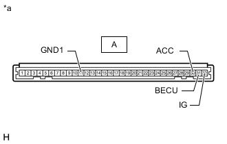
Standard Voltage Tester Connection Condition Specified Condition A-31 (BECU) - Body ground Always 11 to 14 V A-32 (IG) - Body ground Engine switch on (IG) 11 to 14 V A-30 (ACC) - Body ground Engine switch on (ACC) 11 to 14 V -
Measure the resistance according to the value(s) in the table below.
Standard Resistance Tester Connection Condition Specified Condition A-11 (GND1) - Body ground Always Below 1 Ω Result Proceed to OK NG
OK 
REPLACE MAIN BODY ECU (MULTIPLEX NETWORK BODY ECU) Click here
NG
-
-
CHECK HARNESS AND CONNECTOR (INSTRUMENT PANEL JUNCTION BLOCK ASSEMBLY - BATTERY AND BODY GROUND)
-
Disconnect the instrument panel junction block assembly connectors.
*a Front view of wire harness connector
(to Instrument Panel Junction Block Assembly)
- - -
Measure the voltage according to the value(s) in the table below.
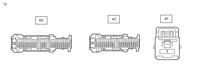
Standard Voltage Tester Connection Condition Specified Condition 4D-49 - Body ground Always 11 to 14 V 4F-1 - Body ground Always 11 to 14 V 4C-28 - Body ground Engine switch on (ACC) 11 to 14 V 4C-44 - Body ground Engine switch on (IG) 11 to 14 V -
Measure the resistance according to the value(s) in the table below.
Standard Resistance Tester Connection Condition Specified Condition 4D-9 - Body ground Always Below 1 Ω Result Proceed to OK NG
OK
REPLACE INSTRUMENT PANEL JUNCTION BLOCK ASSEMBLY Click here
NG
REPAIR OR REPLACE HARNESS OR CONNECTOR
-
-
CHECK FOR OPEN IN CAN BUS MAIN WIRE (NO. 5 CAN JUNCTION CONNECTOR)
-
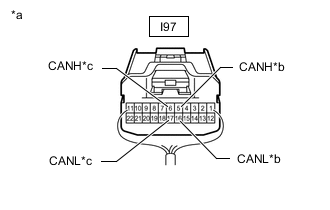
*a Rear view of wire harness connector
(to No. 5 CAN Junction Connector)
*b to No. 7 CAN Junction Connector *c to No. 4 CAN Junction Connector Disconnect the No. 5 CAN junction connector.
-
Measure the resistance according to the value(s) in the table below.
Standard Resistance Tester Connection Condition Specified Condition I97-5 (CANH) - I97-16 (CANL) Cable disconnected from negative (-) battery terminal 108 to 132 Ω I97-6 (CANH) - I97-17 (CANL) Cable disconnected from negative (-) battery terminal 108 to 132 Ω Result Result Proceed to OK A NG (to No. 7 CAN junction connector CAN main wire) B NG (to No. 4 CAN junction connector CAN main wire) C
A
REPLACE NO. 5 CAN JUNCTION CONNECTOR
C
CONNECT CONNECTOR Click here
B
-
-
CONNECT CONNECTOR
-
Reconnect the No. 5 CAN junction connector.
Result Proceed to NEXT
NEXT
-
-
CHECK FOR OPEN IN CAN BUS MAIN WIRE (NO. 7 CAN JUNCTION CONNECTOR)
-
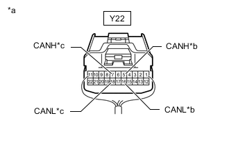
*a Rear view of wire harness connector
(to No. 7 CAN Junction Connector)
*b to No. 5 CAN Junction Connector *c to No. 2 CAN Junction Terminal Disconnect the No. 7 CAN junction connector.
-
Measure the resistance according to the value(s) in the table below.
Standard Resistance Tester Connection Condition Specified Condition Y22-5 (CANH) - Y22-16 (CANL) Cable disconnected from negative (-) battery terminal 108 to 132 Ω Y22-7 (CANH) - Y22-18 (CANL) Cable disconnected from negative (-) battery terminal 108 to 132 Ω Result Result Proceed to OK A NG (to No. 2 CAN junction terminal CAN main wire) B NG (to No. 5 CAN junction connector CAN main wire) C
A
REPLACE NO. 7 CAN JUNCTION CONNECTOR
C
REPAIR OR REPLACE CAN MAIN WIRE OR CONNECTOR (NO. 7 CAN JUNCTION CONNECTOR - NO. 5 CAN JUNCTION CONNECTOR)
B
-
-
CONNECT CONNECTOR
-
Reconnect the No. 7 CAN junction connector.
Result Proceed to NEXT
NEXT
-
-
CHECK FOR OPEN IN CAN BUS MAIN WIRE (NO. 2 CAN JUNCTION TERMINAL)
-
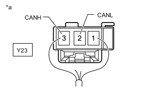
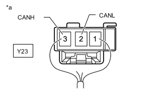
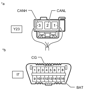
*a Rear view of wire harness connector
(to No. 2 CAN Junction Terminal)
Disconnect the No. 2 CAN junction terminal connector.
-
Measure the resistance according to the value(s) in the table below.
Standard Resistance Tester Connection Condition Specified Condition Y23-3 (CANH) - Y23-2 (CANL) Cable disconnected from negative (-) battery terminal 108 to 132 Ω Result Proceed to OK NG
OK
REPLACE NO. 2 CAN JUNCTION TERMINAL
NG
REPAIR OR REPLACE CAN MAIN WIRE OR CONNECTOR (NO. 2 CAN JUNCTION TERMINAL - NO. 7 CAN JUNCTION CONNECTOR)
-
-
CONNECT CONNECTOR
-
Reconnect the No. 5 CAN junction connector.
Result Proceed to NEXT
NEXT
-
-
CHECK FOR OPEN IN CAN BUS MAIN WIRE (NO. 4 CAN JUNCTION CONNECTOR)
-
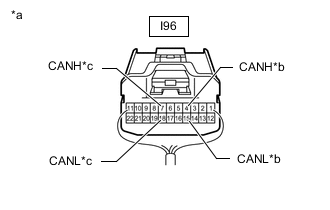
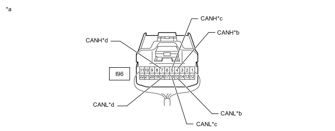
*a Rear view of wire harness connector
(to No. 4 CAN Junction Connector)
*b to Main Body ECU (Multiplex Network Body ECU) *c to No. 5 CAN Junction Connector Disconnect the No. 4 CAN junction connector.
-
Measure the resistance according to the value(s) in the table below.
Standard Resistance Tester Connection Condition Specified Condition I96-4 (CANH) - I96-15 (CANL) Cable disconnected from negative (-) battery terminal 108 to 132 Ω I96-7 (CANH) - I96-18 (CANL) Cable disconnected from negative (-) battery terminal 108 to 132 Ω Result Result Proceed to OK A NG (to main body ECU [multiplex network body ECU] CAN main wire) B NG (to No. 5 CAN junction connector CAN main wire) C
A
REPLACE NO. 4 CAN JUNCTION CONNECTOR
C
REPAIR OR REPLACE CAN MAIN WIRE OR CONNECTOR (NO. 4 CAN JUNCTION CONNECTOR - NO. 5 CAN JUNCTION CONNECTOR)
B
-
-
CONNECT CONNECTOR
-
Reconnect the No. 4 CAN junction connector.
Result Proceed to NEXT
NEXT
-
-
CHECK FOR OPEN IN CAN BUS MAIN WIRE (MAIN BODY ECU)
-
*a Rear view of wire harness connector
(to Main Body ECU [Multiplex Network Body ECU])
Disconnect the main body ECU (multiplex network body ECU) connector.
-
Measure the resistance according to the value(s) in the table below.
Standard Resistance Tester Connection Condition Specified Condition I47-9 (CANP) - I47-10 (CANN) Cable disconnected from negative (-) battery terminal 108 to 132 Ω Result Proceed to OK NG
OK
REPLACE MAIN BODY ECU (MULTIPLEX NETWORK BODY ECU) Click here
NG
REPAIR OR REPLACE CAN MAIN WIRE OR CONNECTED TO MAIN BODY ECU (MAIN BODY ECU - NO. 4 CAN JUNCTION CONNECTOR)
-
-
CHECK FOR SHORT IN CAN BUS WIRES (NO. 7 CAN JUNCTION CONNECTOR)
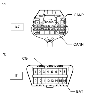
-
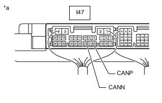
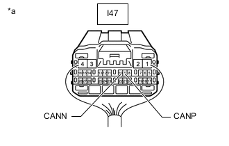
*a Component with harness connected
(to Main Body ECU [Multiplex Network Body ECU])
Disconnect the Y22 No. 7 CAN junction connector.
-
Measure the resistance according to the value(s) in the table below.
Standard Resistance Tester Connection Condition Specified Condition I47-9 (CANP) - I47-10 (CANN) Cable disconnected from negative (-) battery terminal 108 to 132 Ω Result Proceed to OK NG
NG
CONNECT CONNECTOR Click here
OK
-
-
CHECK FOR SHORT IN CAN BUS WIRES (NO. 7 CAN JUNCTION CONNECTOR)
-
Measure the resistance according to the value(s) in the table below.
*a Rear view of wire harness connector
(to No. 7 CAN Junction Connector)
*b to Multiplex Network Door ECU (w/ Power Back Door System) *c to No. 2 CAN Junction Terminal - - Standard Resistance *: w/ Power Back Door SystemTester Connection Condition Specified Condition Y22-6 (CANH) - Y22-17 (CANL)* Cable disconnected from negative (-) battery terminal 200 Ω or higher Y22-7 (CANH) - Y22-18 (CANL) Cable disconnected from negative (-) battery terminal 108 to 132 Ω
Result Result Proceed to OK A NG (to multiplex network door ECU CAN branch wire) (w/ Power Back Door System) B NG (to No. 2 CAN junction terminal CAN main wire) C
A
REPLACE NO. 7 CAN JUNCTION CONNECTOR
C
CONNECT CONNECTOR Click here
B
-
-
CONNECT CONNECTOR
-
Reconnect the No. 7 CAN junction connector.
Result Proceed to NEXT
NEXT
-
-
CHECK FOR SHORT IN CAN BUS WIRES (MULTIPLEX NETWORK DOOR ECU)
-
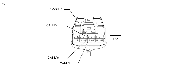
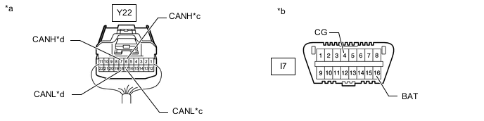
*a Front view of wire harness connector
(to Multiplex Network Door ECU)
Disconnect the multiplex network door ECU connector.
-
Measure the resistance according to the value(s) in the table below.
Standard Resistance Tester Connection Condition Specified Condition Y25-39 (CANP) - Y25-40 (CANN) Cable disconnected from negative (-) battery terminal 54 to 69 Ω Result Proceed to OK NG
OK
REPLACE MULTIPLEX NETWORK DOOR ECU Click here
NG
REPAIR OR REPLACE CAN BRANCH WIRE CONNECTED TO MULTIPLEX NETWORK DOOR ECU (CANP, CANN)
-
-
CONNECT CONNECTOR
-
Reconnect the No. 7 CAN junction connector.
Result Proceed to NEXT
NEXT
-
-
CHECK FOR SHORT IN CAN BUS WIRES (NO. 2 CAN JUNCTION TERMINAL)
-
*a Rear view of wire harness connector
(to No. 2 CAN Junction Terminal)
Disconnect the No. 2 CAN junction terminal connector.
-
Measure the resistance according to the value(s) in the table below.
Standard Resistance Tester Connection Condition Specified Condition Y23-3 (CANH) - Y23-2 (CANL) Cable disconnected from negative (-) battery terminal 108 to 132 Ω Result Proceed to OK NG
OK
REPLACE NO. 2 CAN JUNCTION TERMINAL
NG
REPAIR OR REPLACE CAN MAIN WIRE OR CONNECTOR (NO. 2 CAN JUNCTION TERMINAL - NO. 7 CAN JUNCTION CONNECTOR)
-
-
CONNECT CONNECTOR
-
Reconnect the No. 7 CAN junction connector.
Result Proceed to NEXT
NEXT
-
-
CHECK FOR SHORT IN CAN BUS WIRES (NO. 5 CAN JUNCTION CONNECTOR)
-
*a Component with harness connected
(to Main Body ECU [Multiplex Network Body ECU])
Disconnect the I97 No. 5 CAN junction connector.
-
Measure the resistance according to the value(s) in the table below.
Standard Resistance Tester Connection Condition Specified Condition I47-9 (CANP) - I47-10 (CANN) Cable disconnected from negative (-) battery terminal 108 to 132 Ω Result Proceed to OK NG
NG
CONNECT CONNECTOR Click here
OK
-
-
CHECK FOR SHORT IN CAN BUS WIRES (NO. 5 CAN JUNCTION CONNECTOR)
-
Measure the resistance according to the value(s) in the table below.
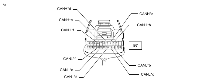
*a Rear view of wire harness connector
(to No. 5 CAN Junction Connector)
*b to Headlight Light Control ECU Sub-assembly LH *c to Multiplex Tilt and Telescopic ECU (for Power Tilt and Power Telescopic Steering Column) *d to No. 7 CAN Junction Connector *e to Front Power Seat Switch LH (w/ Memory) *f to Outer Mirror Control ECU Assembly LH (w/ Memory) Standard Resistance *1: for Power Tilt and Power Telescopic Steering ColumnTester Connection Condition Specified Condition I97-3 (CANH) - I97-14 (CANL) Cable disconnected from negative (-) battery terminal 200 Ω or higher I97-4 (CANH) - I97-15 (CANL)*1 Cable disconnected from negative (-) battery terminal 200 Ω or higher I97-5 (CANH) - I97-16 (CANL) Cable disconnected from negative (-) battery terminal 108 to 132 Ω I97-7 (CANH) - I97-18 (CANL)*2 Cable disconnected from negative (-) battery terminal 200 Ω or higher I97-8 (CANH) - I97-19 (CANL)*2 Cable disconnected from negative (-) battery terminal 200 Ω or higher
*2: w/ Memory
Result Result Proceed to OK A NG (to headlight light control ECU sub-assembly LH CAN branch wire) B NG (to multiplex tilt and telescopic ECU CAN branch wire) (for Power Tilt and Power Telescopic Steering Column) C NG (to front power seat switch LH CAN branch wire) (w/ Memory) D NG (to outer mirror control ECU assembly LH CAN branch wire) (w/ Memory) E NG (to No. 7 CAN junction connector CAN main wire) F
A
REPLACE NO. 5 CAN JUNCTION CONNECTOR
C
CONNECT CONNECTOR Click here
D
CONNECT CONNECTOR Click here
E
CONNECT CONNECTOR Click here
F
REPAIR OR REPLACE CAN MAIN WIRE OR CONNECTOR (NO. 5 CAN JUNCTION CONNECTOR - NO. 7 CAN JUNCTION CONNECTOR)
B
-
-
CONNECT CONNECTOR
-
Reconnect the No. 5 CAN junction connector.
Result Proceed to NEXT
NEXT
-
-
CHECK FOR SHORT IN CAN BUS WIRES (HEADLIGHT LIGHT CONTROL ECU SUB-ASSEMBLY LH)
-
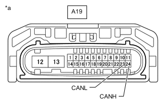
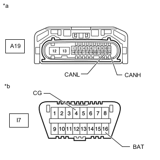
*a Front view of wire harness connector
(to Headlight Light Control ECU Sub-assembly LH)
Disconnect the headlight light control ECU sub-assembly LH connector.
-
Measure the resistance according to the value(s) in the table below.
Standard Resistance Tester Connection Condition Specified Condition A19-24 (CANH) - A19-23 (CANL) Cable disconnected from negative (-) battery terminal 54 to 69 Ω Result Proceed to OK NG
OK
REPLACE HEADLIGHT LIGHT CONTROL ECU SUB-ASSEMBLY LH Click here
NG
REPAIR OR REPLACE CAN BRANCH WIRE CONNECTED TO HEADLIGHT LIGHT CONTROL ECU SUB-ASSEMBLY LH (CANH, CANL)
-
-
CONNECT CONNECTOR
-
Reconnect the No. 5 CAN junction connector.
Result Proceed to NEXT
NEXT
-
-
CHECK FOR SHORT IN CAN BUS WIRES (MULTIPLEX TILT AND TELESCOPIC ECU)
-
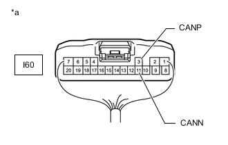
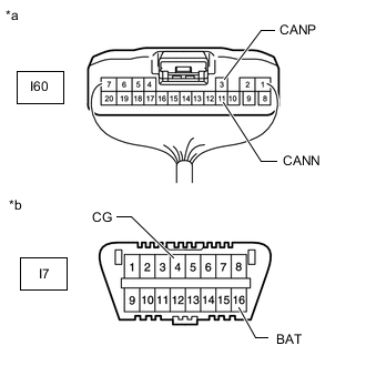
*a Rear view of wire harness connector
(to Multiplex Tilt and Telescopic ECU)
Disconnect the multiplex tilt and telescopic ECU connector.
-
Measure the resistance according to the value(s) in the table below.
Standard Resistance Tester Connection Condition Specified Condition I60-3 (CANP) - I60-11 (CANN) Cable disconnected from negative (-) battery terminal 54 to 69 Ω Result Proceed to OK NG
OK
REPLACE MULTIPLEX TILT AND TELESCOPIC ECU Click here
NG
REPAIR OR REPLACE CAN BRANCH WIRE CONNECTED TO MULTIPLEX TILT AND TELESCOPIC ECU (CANP, CANN)
-
-
CONNECT CONNECTOR
-
Reconnect the No. 5 CAN junction connector.
Result Proceed to NEXT
NEXT
-
-
CHECK FOR SHORT IN CAN BUS WIRES (FRONT POWER SEAT SWITCH LH)
-
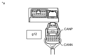
*a Rear view of wire harness connector
(to Front Power Seat Switch LH)
Disconnect the front power seat switch LH connector.
-
Measure the resistance according to the value(s) in the table below.
Standard Resistance Tester Connection Condition Specified Condition g12-8 (CANP) - g12-7 (CANN) Cable disconnected from negative (-) battery terminal 54 to 69 Ω Result Proceed to OK NG
OK
REPLACE FRONT POWER SEAT SWITCH LH Click here
NG
REPAIR OR REPLACE CAN BRANCH WIRE CONNECTED TO FRONT POWER SEAT SWITCH LH (CANP, CANN)
-
-
CONNECT CONNECTOR
-
Reconnect the No. 5 CAN junction connector.
Result Proceed to NEXT
NEXT
-
-
CHECK FOR SHORT IN CAN BUS WIRES (OUTER MIRROR CONTROL ECU ASSEMBLY LH)
-
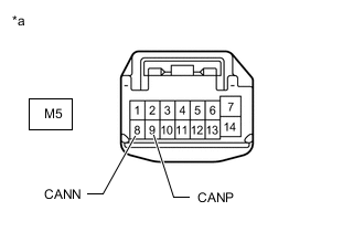
*a Front view of wire harness connector
(to Outer Mirror Control ECU Assembly LH)
Disconnect the outer mirror control ECU assembly LH connector.
-
Measure the resistance according to the value(s) in the table below.
Standard Resistance Tester Connection Condition Specified Condition M5-9 (CANP) - M5-8 (CANN) Cable disconnected from negative (-) battery terminal 54 to 69 Ω Result Proceed to OK NG
OK
REPLACE OUTER MIRROR CONTROL ECU ASSEMBLY LH Click here
NG
REPAIR OR REPLACE CAN BRANCH WIRE CONNECTED TO OUTER MIRROR CONTROL ECU ASSEMBLY LH (CANP, CANN)
-
-
CONNECT CONNECTOR
-
Reconnect the No. 5 CAN junction connector.
Result Proceed to NEXT
NEXT
-
-
CHECK FOR SHORT IN CAN BUS WIRES (NO. 4 CAN JUNCTION CONNECTOR)
-
Disconnect the No. 4 CAN junction connector.
*a Rear view of wire harness connector
(to No. 4 CAN Junction Connector)
*b to Main Body ECU (Multiplex Network Body ECU) *c to Outer Mirror Control ECU Assembly RH (w/ Memory) *d to No. 5 CAN Junction Connector -
Measure the resistance according to the value(s) in the table below.
Standard Resistance *: w/ MemoryTester Connection Condition Specified Condition I96-4 (CANH) - I96-15 (CANL) Cable disconnected from negative (-) battery terminal 108 to 132 Ω I96-5 (CANH) - I96-16 (CANL)* Cable disconnected from negative (-) battery terminal 200 Ω or higher I96-7 (CANH) - I96-18 (CANL) Cable disconnected from negative (-) battery terminal 108 to 132 Ω
Result Result Proceed to OK A NG (to main body ECU [multiplex network body ECU] CAN main wire) B NG (to outer mirror control ECU assembly CAN branch wire) (w/ Memory) C NG (to No. 5 CAN junction connector CAN main wire) D
A
REPLACE NO. 4 CAN JUNCTION CONNECTOR
C
CONNECT CONNECTOR Click here
D
REPAIR OR REPLACE CAN MAIN WIRE OR CONNECTOR (NO. 4 CAN JUNCTION CONNECTOR - NO. 5 CAN JUNCTION CONNECTOR)
B
-
-
CONNECT CONNECTOR
-
Reconnect the No. 4 CAN junction connector.
Result Proceed to NEXT
NEXT
-
-
CHECK FOR SHORT IN CAN BUS WIRES (MAIN BODY ECU)
-
*a Rear view of wire harness connector
(to Main Body ECU [Multiplex Network Body ECU])
Disconnect the main body ECU (multiplex network body ECU) connector.
-
Measure the resistance according to the value(s) in the table below.
Standard Resistance Tester Connection Condition Specified Condition I47-9 (CANP) - I47-10 (CANN) Cable disconnected from negative (-) battery terminal 108 to 132 Ω Result Proceed to OK NG
OK
REPLACE MAIN BODY ECU (MULTIPLEX NETWORK BODY ECU) Click here
NG
REPAIR OR REPLACE CAN MAIN WIRE CONNECTED TO MAIN BODY ECU (CANP, CANN)
-
-
CONNECT CONNECTOR
-
Reconnect the No. 4 CAN junction connector.
Result Proceed to NEXT
NEXT
-
-
CHECK FOR SHORT IN CAN BUS WIRES (OUTER MIRROR CONTROL ECU ASSEMBLY RH)
-
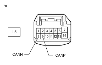
*a Front view of wire harness connector
(to Outer Mirror Control ECU Assembly RH)
Disconnect the outer mirror control ECU assembly RH connector.
-
Measure the resistance according to the value(s) in the table below.
Standard Resistance Tester Connection Condition Specified Condition L5-9 (CANP) - L5-8 (CANN) Cable disconnected from negative (-) battery terminal 54 to 69 Ω Result Proceed to OK NG
OK
REPLACE OUTER MIRROR CONTROL ECU ASSEMBLY RH Click here
NG
REPAIR OR REPLACE CAN BRANCH WIRE CONNECTED TO OUTER MIRROR CONTROL ECU ASSEMBLY RH (CANP, CANN)
-
-
CHECK FOR SHORT IN CAN BUS WIRES (NO. 7 CAN JUNCTION CONNECTOR)
-
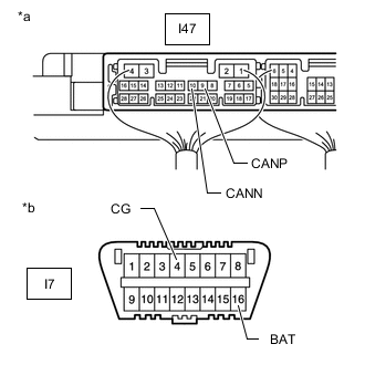
*a Component with harness connected
(to Main Body ECU [Multiplex Network Body ECU])
*b Front view of DLC3 Disconnect the Y22 No. 7 CAN junction connector.
-
Measure the resistance according to the value(s) in the table below.
Standard Resistance Tester Connection Condition Specified Condition I47-9 (CANP) - I7-4 (CG) Cable disconnected from negative (-) battery terminal 200 Ω or higher I47-10 (CANN) - I7-4 (CG) Cable disconnected from negative (-) battery terminal 200 Ω or higher I47-9 (CANP) - I7-16 (BAT) Cable disconnected from negative (-) battery terminal 6 kΩ or higher I47-10 (CANN) - I7-16 (BAT) Cable disconnected from negative (-) battery terminal 6 kΩ or higher Result Proceed to OK NG
NG
CONNECT CONNECTOR Click here
OK
-
-
CHECK FOR SHORT IN CAN BUS WIRES (NO. 7 CAN JUNCTION CONNECTOR)
-
Measure the resistance according to the value(s) in the table below.
*a Rear view of wire harness connector
(to No. 7 CAN Junction Connector)
*b Front view of DLC3 *c to Multiplex Network Door ECU (w/ Power Back Door System) *d to No. 2 CAN Junction Terminal Standard Resistance *: w/ Power Back Door SystemTester Connection Condition Specified Condition Y22-6 (CANH) - I7-4 (CG)* Cable disconnected from negative (-) battery terminal 200 Ω or higher Y22-17 (CANL) - I7-4 (CG)* Cable disconnected from negative (-) battery terminal 200 Ω or higher Y22-6 (CANH) - I7-16 (BAT)* Cable disconnected from negative (-) battery terminal 6 kΩ or higher Y22-17 (CANL) - I7-16 (BAT)* Cable disconnected from negative (-) battery terminal 6 kΩ or higher Y22-7 (CANH) - I7-4 (CG) Cable disconnected from negative (-) battery terminal 200 Ω or higher Y22-18 (CANL) - I7-4 (CG) Cable disconnected from negative (-) battery terminal 200 Ω or higher Y22-7 (CANH) - I7-16 (BAT) Cable disconnected from negative (-) battery terminal 6 kΩ or higher Y22-18 (CANL) - I7-16 (BAT) Cable disconnected from negative (-) battery terminal 6 kΩ or higher
Result Result Proceed to OK A NG (to multiplex network door ECU CAN branch wire) (w/ Power Back Door System) B NG (to No. 2 CAN junction terminal CAN main wire) C
A
REPLACE NO. 7 CAN JUNCTION CONNECTOR
C
CONNECT CONNECTOR Click here
B
-
-
CONNECT CONNECTOR
-
Reconnect the No. 7 CAN junction connector.
Result Proceed to NEXT
NEXT
-
-
CHECK FOR SHORT IN CAN BUS WIRES (MULTIPLEX NETWORK DOOR ECU)
-
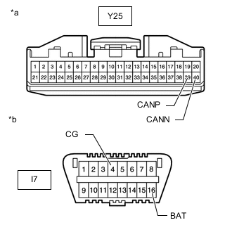
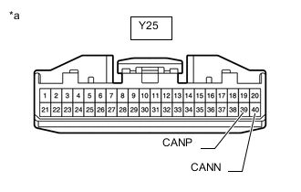
*a Front view of wire harness connector
(to Multiplex Network Door ECU)
*b Front view of DLC3 Disconnect the multiplex network door ECU connector.
-
Measure the resistance according to the value(s) in the table below.
Standard Resistance Tester Connection Condition Specified Condition Y25-39 (CANP) - I7-4 (CG) Cable disconnected from negative (-) battery terminal 200 Ω or higher Y25-40 (CANN) - I7-4 (CG) Cable disconnected from negative (-) battery terminal 200 Ω or higher Y25-39 (CANP) - I7-16 (BAT) Cable disconnected from negative (-) battery terminal 6 kΩ or higher Y25-40 (CANN) - I7-16 (BAT) Cable disconnected from negative (-) battery terminal 6 kΩ or higher Result Proceed to OK NG
OK
REPLACE MULTIPLEX NETWORK DOOR ECU Click here
NG
REPAIR OR REPLACE CAN BRANCH WIRE CONNECTED TO MULTIPLEX NETWORK DOOR ECU (CANP, CANN)
-
-
CONNECT CONNECTOR
-
Reconnect the No. 7 CAN junction connector.
Result Proceed to NEXT
NEXT
-
-
CHECK FOR SHORT IN CAN BUS WIRES (NO. 2 CAN JUNCTION TERMINAL)
-
*a Rear view of wire harness connector
(to No. 2 CAN Junction Terminal)
*b Front view of DLC3 Disconnect the No. 2 CAN junction terminal connector.
-
Measure the resistance according to the value(s) in the table below.
Standard Resistance Tester Connection Condition Specified Condition Y23-3 (CANH) - I7-4 (CG) Cable disconnected from negative (-) battery terminal 200 Ω or higher Y23-2 (CANL) - I7-4 (CG) Cable disconnected from negative (-) battery terminal 200 Ω or higher Y23-3 (CANH) - I7-16 (BAT) Cable disconnected from negative (-) battery terminal 6 kΩ or higher Y23-2 (CANL) - I7-16 (BAT) Cable disconnected from negative (-) battery terminal 6 kΩ or higher Result Proceed to OK NG
OK
REPLACE NO. 2 CAN JUNCTION TERMINAL
NG
REPAIR OR REPLACE CAN MAIN WIRE OR CONNECTOR (NO. 2 CAN JUNCTION TERMINAL - NO. 7 CAN JUNCTION CONNECTOR)
-
-
CONNECT CONNECTOR
-
Reconnect the No. 7 CAN junction connector.
Result Proceed to NEXT
NEXT
-
-
CHECK FOR SHORT IN CAN BUS WIRES (NO. 5 CAN JUNCTION CONNECTOR)
-
*a Component with harness connected
(to Main Body ECU [Multiplex Network Body ECU])
*b Front view of DLC3 Disconnect I97 the No. 5 CAN junction connector.
-
Measure the resistance according to the value(s) in the table below.
Standard Resistance Tester Connection Condition Specified Condition I47-9 (CANP) - I7-4 (CG) Cable disconnected from negative (-) battery terminal 200 Ω or higher I47-10 (CANN) - I7-4 (CG) Cable disconnected from negative (-) battery terminal 200 Ω or higher I47-9 (CANP) - I7-16 (BAT) Cable disconnected from negative (-) battery terminal 6 kΩ or higher I47-10 (CANN) - I7-16 (BAT) Cable disconnected from negative (-) battery terminal 6 kΩ or higher Result Proceed to OK NG
NG
CONNECT CONNECTOR Click here
OK
-
-
CHECK FOR SHORT IN CAN BUS WIRES (NO. 5 CAN JUNCTION CONNECTOR)
-
Measure the resistance according to the value(s) in the table below.
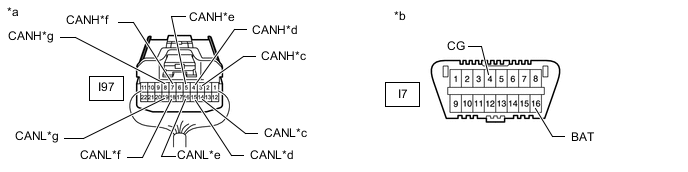
*a Rear view of wire harness connector
(to No. 5 CAN Junction Connector)
*b Front view of DLC3 *c to Headlight Light Control ECU Sub-assembly LH *d to Multiplex Tilt and Telescopic ECU (for Power Tilt and Power Telescopic Steering Column) *e to No. 7 CAN Junction Connector *f to Front Power Seat Switch LH (w/ Memory) *g to Outer Mirror Control ECU Assembly LH (w/ Memory) - - Standard Resistance *1: for Power Tilt and Power Telescopic Steering ColumnTester Connection Condition Specified Condition I97-3 (CANH) - I7-4 (CG) Cable disconnected from negative (-) battery terminal 200 Ω or higher I97-14 (CANL) - I7-4 (CG) Cable disconnected from negative (-) battery terminal 200 Ω or higher I97-3 (CANH) - I7-16 (BAT) Cable disconnected from negative (-) battery terminal 6 kΩ or higher I97-14 (CANL) - I7-16 (BAT) Cable disconnected from negative (-) battery terminal 6 kΩ or higher I97-4 (CANH) - I7-4 (CG)*1 Cable disconnected from negative (-) battery terminal 200 Ω or higher I97-15 (CANL) - I7-4 (CG)*1 Cable disconnected from negative (-) battery terminal 200 Ω or higher I97-4 (CANH) - I7-16 (BAT)*1 Cable disconnected from negative (-) battery terminal 6 kΩ or higher I97-15 (CANL) - I7-16 (BAT)*1 Cable disconnected from negative (-) battery terminal 6 kΩ or higher I97-5 (CANH) - I7-4 (CG) Cable disconnected from negative (-) battery terminal 200 Ω or higher I97-16 (CANL) - I7-4 (CG) Cable disconnected from negative (-) battery terminal 200 Ω or higher I97-5 (CANH) - I7-16 (BAT) Cable disconnected from negative (-) battery terminal 6 kΩ or higher I97-16 (CANL) - I7-16 (BAT) Cable disconnected from negative (-) battery terminal 6 kΩ or higher I97-7 (CANH) - I7-4 (CG)*2 Cable disconnected from negative (-) battery terminal 200 Ω or higher I97-18 (CANL) - I7-4 (CG)*2 Cable disconnected from negative (-) battery terminal 200 Ω or higher I97-7 (CANH) - I7-16 (BAT)*2 Cable disconnected from negative (-) battery terminal 6 kΩ or higher I97-18 (CANL) - I7-16 (BAT)*2 Cable disconnected from negative (-) battery terminal 6 kΩ or higher I97-8 (CANH) - I7-4 (CG)*2 Cable disconnected from negative (-) battery terminal 200 Ω or higher I97-19 (CANL) - I7-4 (CG)*2 Cable disconnected from negative (-) battery terminal 200 Ω or higher I97-8 (CANH) - I7-16 (BAT)*2 Cable disconnected from negative (-) battery terminal 6 kΩ or higher I97-19 (CANL) - I7-16 (BAT)*2 Cable disconnected from negative (-) battery terminal 6 kΩ or higher
*2: w/ Memory
Result Result Proceed to OK A NG (to headlight light control ECU sub-assembly LH CAN branch wire) B NG (to multiplex tilt and telescopic ECU CAN branch wire) (for Power Tilt and Power Telescopic Steering Column) C NG (to front power seat switch LH CAN branch wire) (w/ Memory) D NG (to outer mirror control ECU assembly LH CAN branch wire) (w/ Memory) E NG (to No. 7 CAN junction connector CAN main wire) F
A
REPLACE NO. 5 CAN JUNCTION CONNECTOR
C
CONNECT CONNECTOR Click here
D
CONNECT CONNECTOR Click here
E
CONNECT CONNECTOR Click here
F
REPAIR OR REPLACE CAN MAIN WIRE OR CONNECTOR (NO. 5 CAN JUNCTION CONNECTOR - NO. 7 CAN JUNCTION CONNECTOR)
B
-
-
CONNECT CONNECTOR
-
Reconnect the No. 5 CAN junction connector.
Result Proceed to NEXT
NEXT
-
-
CHECK FOR SHORT IN CAN BUS WIRES (HEADLIGHT LIGHT CONTROL ECU SUB-ASSEMBLY LH)
-
*a Front view of wire harness connector
(to Headlight Light Control ECU Sub-assembly LH)
*b Front view of DLC3 Disconnect the headlight light control ECU sub-assembly LH connector.
-
Measure the resistance according to the value(s) in the table below.
Standard Resistance Tester Connection Condition Specified Condition A19-24 (CANH) - I7-4 (CG) Cable disconnected from negative (-) battery terminal 200 Ω or higher A19-23 (CANL) - I7-4 (CG) Cable disconnected from negative (-) battery terminal 200 Ω or higher A19-24 (CANH) - I7-16 (BAT) Cable disconnected from negative (-) battery terminal 6 kΩ or higher A19-23 (CANL) - I7-16 (BAT) Cable disconnected from negative (-) battery terminal 6 kΩ or higher Result Proceed to OK NG
OK
REPLACE HEADLIGHT LIGHT CONTROL ECU SUB-ASSEMBLY LH Click here
NG
REPAIR OR REPLACE CAN BRANCH WIRE CONNECTED TO HEADLIGHT LIGHT CONTROL ECU SUB-ASSEMBLY LH (CANH, CANL)
-
-
CONNECT CONNECTOR
-
Reconnect the No. 5 CAN junction connector.
Result Proceed to NEXT
NEXT
-
-
CHECK FOR SHORT IN CAN BUS WIRES (MULTIPLEX TILT AND TELESCOPIC ECU)
-
*a Rear view of wire harness connector
(to Multiplex Tilt and Telescopic ECU)
*b Front view of DLC3 Disconnect the multiplex tilt and telescopic ECU connector.
-
Measure the resistance according to the value(s) in the table below.
Standard Resistance Tester Connection Condition Specified Condition I60-3 (CANP) - I7-4 (CG) Cable disconnected from negative (-) battery terminal 200 Ω or higher I60-11 (CANN) - I7-4 (CG) Cable disconnected from negative (-) battery terminal 200 Ω or higher I60-3 (CANP) - I7-16 (BAT) Cable disconnected from negative (-) battery terminal 6 kΩ or higher I60-11 (CANN) - I7-16 (BAT) Cable disconnected from negative (-) battery terminal 6 kΩ or higher Result Proceed to OK NG
OK
REPLACE MULTIPLEX TILT AND TELESCOPIC ECU Click here
NG
REPAIR OR REPLACE CAN BRANCH WIRE CONNECTED TO MULTIPLEX TILT AND TELESCOPIC ECU (CANP, CANN)
-
-
CONNECT CONNECTOR
-
Reconnect the No. 5 CAN junction connector.
Result Proceed to NEXT
NEXT
-
-
CHECK FOR SHORT IN CAN BUS WIRES (FRONT POWER SEAT SWITCH LH)
-
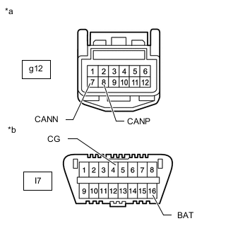
*a Front view of wire harness connector
(to Front Power Seat Switch LH)
*b Front view of DLC3 Disconnect the front power seat switch LH connector.
-
Measure the resistance according to the value(s) in the table below.
Standard Resistance Tester Connection Condition Specified Condition g12-8 (CANP) - I7-4 (CG) Cable disconnected from negative (-) battery terminal 200 Ω or higher g12-7 (CANN) - I7-4 (CG) Cable disconnected from negative (-) battery terminal 200 Ω or higher g12-8 (CANP) - I7-16 (BAT) Cable disconnected from negative (-) battery terminal 6 kΩ or higher g12-7 (CANN) - I7-16 (BAT) Cable disconnected from negative (-) battery terminal 6 kΩ or higher Result Proceed to OK NG
OK
REPLACE FRONT POWER SEAT SWITCH LH Click here
NG
REPAIR OR REPLACE CAN BRANCH WIRE CONNECTED TO FRONT POWER SEAT SWITCH LH (CANP, CANN)
-
-
CONNECT CONNECTOR
-
Reconnect the No. 5 CAN junction connector.
Result Proceed to NEXT
NEXT
-
-
CHECK FOR SHORT IN CAN BUS WIRES (OUTER MIRROR CONTROL ECU ASSEMBLY LH)
-

*a Front view of wire harness connector
(to Outer Mirror Control ECU Assembly LH)
*b Front view of DLC3 Disconnect the outer mirror control ECU assembly LH connector.
-
Measure the resistance according to the value(s) in the table below.
Standard Resistance Tester Connection Condition Specified Condition M5-9 (CANP) - I7-4 (CG) Cable disconnected from negative (-) battery terminal 200 Ω or higher M5-8 (CANN) - I7-4 (CG) Cable disconnected from negative (-) battery terminal 200 Ω or higher M5-9 (CANP) - I7-16 (BAT) Cable disconnected from negative (-) battery terminal 6 kΩ or higher M5-8 (CANN) - I7-16 (BAT) Cable disconnected from negative (-) battery terminal 6 kΩ or higher Result Proceed to OK NG
OK
REPLACE OUTER MIRROR CONTROL ECU ASSEMBLY LH Click here
NG
REPAIR OR REPLACE CAN BRANCH WIRE CONNECTED TO OUTER MIRROR CONTROL ECU ASSEMBLY LH (CANP, CANN)
-
-
CONNECT CONNECTOR
-
Reconnect the No. 5 CAN junction connector.
Result Proceed to NEXT
NEXT
-
-
CHECK FOR SHORT IN CAN BUS WIRES (NO. 4 CAN JUNCTION CONNECTOR)
-
Disconnect the No. 4 CAN junction connector.
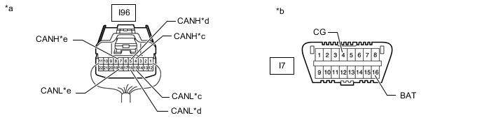
*a Rear view of wire harness connector
(to No. 4 CAN Junction Connector)
*b Front view of DLC3 *c to Main Body ECU (Multiplex Network Body ECU) *d to Outer Mirror Control ECU Assembly RH (w/ Memory) *e to No. 5 CAN Junction Connector - - -
Measure the resistance according to the value(s) in the table below.
Standard Resistance *: w/ MemoryTester Connection Condition Specified Condition I96-4 (CANH) - I7-4 (CG) Cable disconnected from negative (-) battery terminal 200 Ω or higher I96-15 (CANL) - I7-4 (CG) Cable disconnected from negative (-) battery terminal 200 Ω or higher I96-4 (CANH) - I7-16 (BAT) Cable disconnected from negative (-) battery terminal 6 kΩ or higher I96-15 (CANL) - I7-16 (BAT) Cable disconnected from negative (-) battery terminal 6 kΩ or higher I96-5 (CANH) - I7-4 (CG)* Cable disconnected from negative (-) battery terminal 200 Ω or higher I96-16 (CANL) - I7-4 (CG)* Cable disconnected from negative (-) battery terminal 200 Ω or higher I96-5 (CANH) - I7-16 (BAT)* Cable disconnected from negative (-) battery terminal 6 kΩ or higher I96-16 (CANL) - I7-16 (BAT)* Cable disconnected from negative (-) battery terminal 6 kΩ or higher I96-7 (CANH) - I7-4 (CG) Cable disconnected from negative (-) battery terminal 200 Ω or higher I96-18 (CANL) - I7-4 (CG) Cable disconnected from negative (-) battery terminal 200 Ω or higher I96-7 (CANH) - I7-16 (BAT) Cable disconnected from negative (-) battery terminal 6 kΩ or higher I96-18 (CANL) - I7-16 (BAT) Cable disconnected from negative (-) battery terminal 6 kΩ or higher
Result Result Proceed to OK A NG (to main body ECU [multiplex network body ECU] CAN main wire) B NG (to outer mirror control ECU assembly RH CAN branch wire) (w/ Memory) C NG (to No. 5 CAN junction connector CAN main wire) D
A
REPLACE NO. 4 CAN JUNCTION CONNECTOR
C
CONNECT CONNECTOR Click here
D
REPAIR OR REPLACE CAN MAIN WIRE OR CONNECTOR (NO. 4 CAN JUNCTION CONNECTOR - NO. 5 CAN JUNCTION CONNECTOR)
B
-
-
CONNECT CONNECTOR
-
Reconnect the No. 4 CAN junction connector.
Result Proceed to NEXT
NEXT
-
-
CHECK FOR SHORT IN CAN BUS WIRES (MAIN BODY ECU)
-
*a Rear view of wire harness connector
(to Main Body ECU [Multiplex Network Body ECU])
*b Front view of DLC3 Disconnect the main body ECU (multiplex network body ECU) connector.
-
Measure the resistance according to the value(s) in the table below.
Standard Resistance Tester Connection Condition Specified Condition I47-9 (CANP) - I7-4 (CG) Cable disconnected from negative (-) battery terminal 200 Ω or higher I47-10 (CANN) - I7-4 (CG) Cable disconnected from negative (-) battery terminal 200 Ω or higher I47-9 (CANP) - I7-16 (BAT) Cable disconnected from negative (-) battery terminal 6 kΩ or higher I47-10 (CANN) - I7-16 (BAT) Cable disconnected from negative (-) battery terminal 6 kΩ or higher Result Proceed to OK NG
OK
REPLACE MAIN BODY ECU (MULTIPLEX NETWORK BODY ECU) Click here
NG
REPAIR OR REPLACE CAN MAIN WIRE CONNECTED TO MAIN BODY ECU (CANP, CANN)
-
-
CONNECT CONNECTOR
-
Reconnect the No. 4 CAN junction connector.
Result Proceed to NEXT
NEXT
-
-
CHECK FOR SHORT IN CAN BUS WIRES (OUTER MIRROR CONTROL ECU ASSEMBLY RH)
-
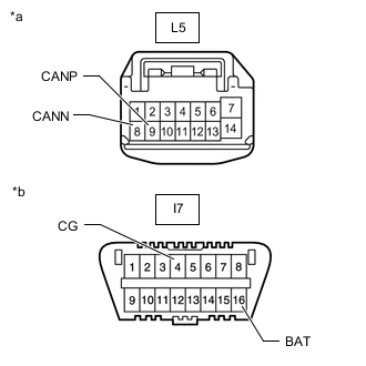
*a Front view of wire harness connector
(to Outer Mirror Control ECU Assembly RH)
*b Front view of DLC3 Disconnect the outer mirror control ECU assembly RH connector.
-
Measure the resistance according to the value(s) in the table below.
Standard Resistance Tester Connection Condition Specified Condition L5-9 (CANP) - I7-4 (CG) Cable disconnected from negative (-) battery terminal 200 Ω or higher L5-8 (CANN) - I7-4 (CG) Cable disconnected from negative (-) battery terminal 200 Ω or higher L5-9 (CANP) - I7-16 (BAT) Cable disconnected from negative (-) battery terminal 6 kΩ or higher L5-8 (CANN) - I7-16 (BAT) Cable disconnected from negative (-) battery terminal 6 kΩ or higher Result Proceed to OK NG
OK
REPLACE OUTER MIRROR CONTROL ECU ASSEMBLY RH Click here
NG
REPAIR OR REPLACE CAN BRANCH WIRE CONNECTED TO OUTER MIRROR CONTROL ECU ASSEMBLY RH (CANP, CANN)
-