CLUTCH UNIT(for Diesel) INSPECTION
PROCEDURE
INSPECT CLUTCH DISC ASSEMBLY
-
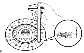
Using a vernier caliper, measure the rivet head depth.
Minimum rivet depth
0.3 mm (0.0118 in.)
If the depth is less than the minimum, replace the clutch disc assembly.
Install the clutch disc assembly to the manual transaxle assembly.
Note:Take care not to insert the clutch disc in the wrong direction.
-
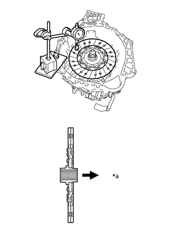
*a
Transaxle Side
Using a dial indicator, measure the clutch disc assembly runout.
Minimum runout
0.8 mm (0.0314 in.)
If the runout is more than the maximum, replace the clutch disc assembly.
-
INSPECT CLUTCH COVER ASSEMBLY
-
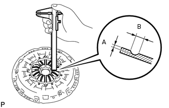
Using a vernier caliper, measure the depth and width of the worn areas of the diaphragm spring.
Maximum depth A
0.5 mm (0.0196 in.)
Maximum width B
6.0 mm (0.236 in.)
If the depth or width is more than the maximum, replace the clutch cover assembly.
-
INSPECT FLYWHEEL SUB-ASSEMBLY
-
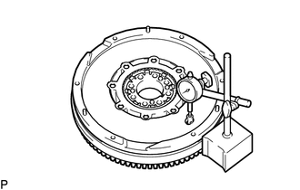
Using a dial indicator, measure the flywheel runout.
Maximum runout
0.1 mm (0.00393 in.)
If the runout is more than the maximum, replace the flywheel sub-assembly.
-
INSPECT CLUTCH RELEASE BEARING ASSEMBLY
-
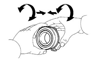
Turn the release bearing by hand while applying force in the axial direction.
Tip:The bearing is permanently lubricated and requires no cleaning or lubrication.
Replace the release bearing assembly as necessary.
-