NAVIGATION SYSTEM, Diagnostic DTC:B15C3
| DTC Code | DTC Name |
|---|---|
| B15C3 | Speaker Output Short |
DESCRIPTION
This DTC is stored when a malfunction occurs in the speakers.
DTC No. |
Detection Item |
DTC Detection Condition |
Trouble Area |
|---|---|---|---|
B15C3 |
Speaker Output Short |
A short is detected in the speaker output circuit |
|
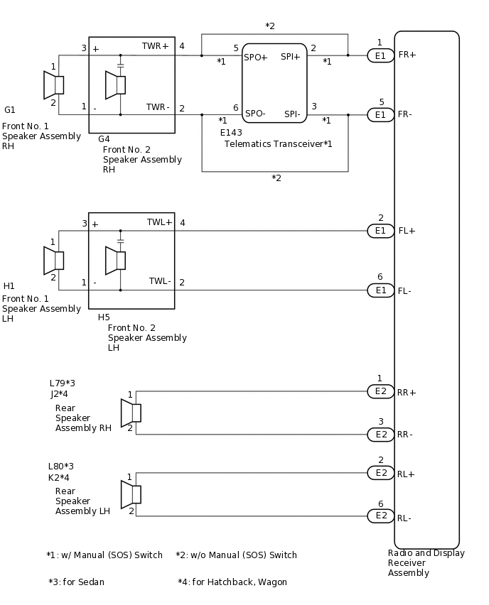
*1: for 6 Speakers
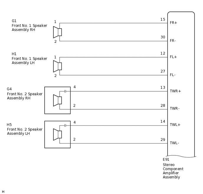
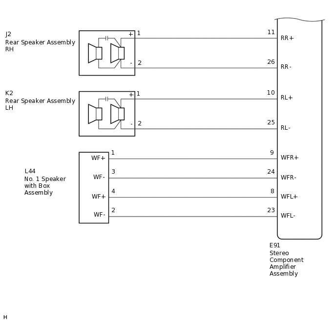
*2: for 9 Speakers
*3: w/ Manual (SOS) Switch
WIRING DIAGRAM
for 6 Speakers
for 9 Speakers
PROCEDURE
CONFIRM MODEL
Choose the model to be inspected.
Result
Result
Proceed to
for 6 Speakers (w/o Manual (SOS) Switch)
A
for 6 Speakers (w/ Manual (SOS) Switch)
B
for 9 Speakers
C
B CHECK HARNESS AND CONNECTOR (RADIO AND DISPLAY RECEIVER ASSEMBLY, TELEMATICS TRANSCEIVER OR SPEAKERS - BODY GROUND)Click here
C CHECK HARNESS AND CONNECTOR (STEREO COMPONENT AMPLIFIER ASSEMBLY - BODY GROUND)Click here
CHECK HARNESS AND CONNECTOR (RADIO AND DISPLAY RECEIVER ASSEMBLY OR SPEAKERS - BODY GROUND)
Disconnect the E1 and E2 radio and display receiver assembly connectors.
Disconnect the G4 and H5 front No. 2 speaker assembly connectors.
Disconnect the L79 and L80 rear speaker assembly connectors (for Sedan).
Disconnect the J2 and K2 rear speaker assembly connectors (for Hatchback, Wagon).
Measure the resistance according to the value(s) in the table below.
Standard Resistance
Tester Connection
Condition
Specified Condition
G4-4 (TWR+) or E1-1 (FR+) - Body ground
Always
10 kΩ or higher
G4-2 (TWR-) or E1-5 (FR-) - Body ground
Always
10 kΩ or higher
H5-4 (TWL+) or E1-2 (FL+) - Body ground
Always
10 kΩ or higher
H5-2 (TWL-) or E1-6 (FL-) - Body ground
Always
10 kΩ or higher
L79-1 or E2-1 (RR+) - Body ground*1
Always
10 kΩ or higher
L79-2 or E2-3 (RR-) - Body ground*1
Always
10 kΩ or higher
L80-1 or E2-2 (RL+) - Body ground*1
Always
10 kΩ or higher
L80-2 or E2-6 (RL-) - Body ground*1
Always
10 kΩ or higher
J2-1 or E2-1 (RR+) - Body ground*2
Always
10 kΩ or higher
J2-2 or E2-3 (RR-) - Body ground*2
Always
10 kΩ or higher
K2-1 or E2-2 (RL+) - Body ground*2
Always
10 kΩ or higher
K2-2 or E2-6 (RL-) - Body ground*2
Always
10 kΩ or higher
*1: for Sedan
*2: for Hatchback, Wagon
Result
Proceed to
OK
NG
NG REPAIR OR REPLACE HARNESS OR CONNECTOR
CHECK HARNESS AND CONNECTOR (FRONT NO. 1 SPEAKER ASSEMBLY OR FRONT NO. 2 SPEAKER ASSEMBLY - BODY GROUND)
Disconnect the G1 and H1 front No. 1 speaker assembly connectors.
Disconnect the G4 and H5 front No. 2 speaker assembly connectors.
Measure the resistance according to the value(s) in the table below.
Standard Resistance
Tester Connection
Condition
Specified Condition
G4-3 (+) or G1-1 - Body ground
Always
10 kΩ or higher
G4-1 (-) or G1-2 - Body ground
Always
10 kΩ or higher
H5-3 (+) or H1-1 - Body ground
Always
10 kΩ or higher
H5-1 (-) or H1-2 - Body ground
Always
10 kΩ or higher
Result
Proceed to
OK
NG
NG REPAIR OR REPLACE HARNESS OR CONNECTOR
INSPECT FRONT NO. 1 SPEAKER ASSEMBLY
Remove the front No. 1 speaker assembly.
for Sedan:Click here
for Hatchback, Wagon:Click here
-
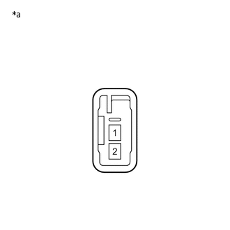
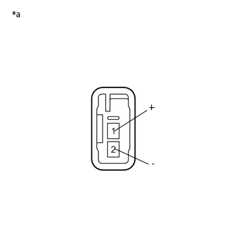
*a
Component without harness connected
(Front No. 1 Speaker Assembly)
Measure the resistance according to the value(s) in the table below.
Standard Resistance
Tester Connection
Condition
Specified Condition
1 - 2
Always
3.2 to 4.8 Ω
Result
Proceed to
OK
NG
INSPECT FRONT NO. 2 SPEAKER ASSEMBLY
Remove the front No. 2 speaker assembly.
for Sedan:Click here
for Hatchback, Wagon:Click here
-
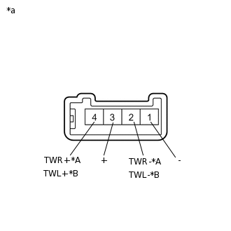
*A
for RH
*B
for LH
*a
Component without harness connected
(Front No. 2 Speaker Assembly)
Measure the resistance according to the value(s) in the table below.
Standard Resistance (for RH)
Tester Connection
Condition
Specified Condition
4 (TWR+) - 2 (TWR-)
Always
10 kΩ or higher
3 (+) - 4 (TWR+)
Always
Below 1 Ω
1 (-) - 2 (TWR-)
Always
Below 1 Ω
Standard Resistance (for LH)
Tester Connection
Condition
Specified Condition
4 (TWL+) - 2 (TWL-)
Always
10 kΩ or higher
3 (+) - 4 (TWL+)
Always
Below 1 Ω
1 (-) - 2 (TWL-)
Always
Below 1 Ω
Result
Proceed to
OK
NG
REPLACE FRONT NO. 2 SPEAKER ASSEMBLY
Replace the front No. 2 speaker assembly with a new or known good one.
for Sedan:Click here
for Hatchback, Wagon:Click here
Clear the DTCs.
Body Electrical > Navigation System > Clear DTCs
Recheck for DTCs and check that no DTCs are output.
Body Electrical > Navigation System > Trouble Codes
OK
No DTCs are output.
Tip:Connect all the connectors to the front No. 2 speaker assemblies that were disconnected.
When there is a possibility that either the right or left front No. 2 speaker assembly is defective, inspect by interchanging the right one with the left one.
Perform the above inspection on both the LH and RH side.
Result
Proceed to
OK
NG
OK END
INSPECT REAR SPEAKER ASSEMBLY
Remove the rear speaker assembly.
for Sedan:Click here
for Hatchback, Wagon:Click here
-
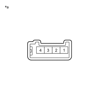
*a
Component without harness connected
(Rear Speaker Assembly)
Measure the resistance according to the value(s) in the table below.
Standard Resistance
Tester Connection
Condition
Specified Condition
1 - 2
Always
3.2 to 4.8 Ω
Result
Proceed to
OK
NG
CHECK HARNESS AND CONNECTOR (RADIO AND DISPLAY RECEIVER ASSEMBLY, TELEMATICS TRANSCEIVER OR SPEAKERS - BODY GROUND)
Disconnect the E1 and E2 radio and display receiver assembly connectors.
Disconnect the E143 telematics transceiver connector.
Disconnect the H5 front No. 2 speaker assembly LH connector.
Disconnect the L79 and L80 rear speaker assembly connectors.
Measure the resistance according to the value(s) in the table below.
Standard Resistance
Tester Connection
Condition
Specified Condition
E1-1 (FR+) or E143-2 (SPI+) - Body ground
Always
10 kΩ or higher
E1-5 (FR-) or E143-3 (SPI-) - Body ground
Always
10 kΩ or higher
E1-2 (FL+) or H5-4 (TWL+) - Body ground
Always
10 kΩ or higher
E1-6 (FL-) or H5-2 (TWL-) - Body ground
Always
10 kΩ or higher
E2-1 (RR+) or L79-1 - Body ground
Always
10 kΩ or higher
E2-3 (RR-) or L79-2 - Body ground
Always
10 kΩ or higher
E2-2 (RL+) or L80-1 - Body ground
Always
10 kΩ or higher
E2-6 (RL-) or L80-2 - Body ground
Always
10 kΩ or higher
Result
Proceed to
OK
NG
NG REPAIR OR REPLACE HARNESS OR CONNECTOR
INSPECT TELEMATICS TRANSCEIVER
Remove the telematics transceiver.
-
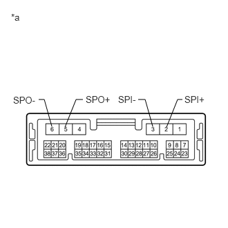
*a
Component without harness connected
(Telematics Transceiver)
Measure the resistance according to the value(s) in the table below.
Standard Resistance
Tester Connection
Condition
Specified Condition
2 (SPI+) - 5 (SPO+)
Always
Below 1 Ω
3 (SPI-) - 6 (SPO-)
Always
Below 1 Ω
2 (SPI+) - 3 (SPI-)
Always
10 kΩ or higher
5 (SPO+) - 6 (SPO-)
Always
10 kΩ or higher
2 (SPI+) or 5 (SPO+) - Body ground
Always
10 kΩ or higher
3 (SPI-) or 6 (SPO-) - Body ground
Always
10 kΩ or higher
Result
Proceed to
OK
NG
CHECK HARNESS AND CONNECTOR (FRONT NO. 2 SPEAKER ASSEMBLY RH OR TELEMATICS TRANSCEIVER - BODY GROUND)
Disconnect the G4 front No. 2 speaker assembly RH connector.
Disconnect the E143 telematics transceiver connector.
Measure the resistance according to the value(s) in the table below.
Standard Resistance
Tester Connection
Condition
Specified Condition
G4-4 (TWR+) or E143-5 (SPO+) - Body ground
Always
10 kΩ or higher
G4-2 (TWR-) or E143-6 (SPO-) - Body ground
Always
10 kΩ or higher
Result
Proceed to
OK
NG
NG REPAIR OR REPLACE HARNESS OR CONNECTOR
CHECK HARNESS AND CONNECTOR (FRONT NO. 1 SPEAKER ASSEMBLY OR FRONT NO. 2 SPEAKER ASSEMBLY - BODY GROUND)
Disconnect the G1 and H1 front No. 1 speaker assembly connectors.
Disconnect the G4 and H5 front No. 2 speaker assembly connectors.
Measure the resistance according to the value(s) in the table below.
Standard Resistance
Tester Connection
Condition
Specified Condition
G4-3 (+) or G1-1 - Body ground
Always
10 kΩ or higher
G4-1 (-) or G1-2 - Body ground
Always
10 kΩ or higher
H5-3 (+) or H1-1 - Body ground
Always
10 kΩ or higher
H5-1 (-) or H1-2 - Body ground
Always
10 kΩ or higher
Result
Proceed to
OK
NG
NG REPAIR OR REPLACE HARNESS OR CONNECTOR
INSPECT FRONT NO. 1 SPEAKER ASSEMBLY
Remove the front No. 1 speaker assembly.
-
*a
Component without harness connected
(Front No. 1 Speaker Assembly)
Measure the resistance according to the value(s) in the table below.
Standard Resistance
Tester Connection
Condition
Specified Condition
1 - 2
Always
3.2 to 4.8 Ω
Result
Proceed to
OK
NG
INSPECT FRONT NO. 2 SPEAKER ASSEMBLY
Remove the front No. 2 speaker assembly.
-
*A
for RH
*B
for LH
*a
Component without harness connected
(Front No. 2 Speaker Assembly)
Measure the resistance according to the value(s) in the table below.
Standard Resistance
Tester Connection
Condition
Specified Condition
4 (TWR+) - 2 (TWR-)
Always
10 kΩ or higher
3 (+) - 4 (TWR+)
Always
Below 1 Ω
1 (-) - 2 (TWR-)
Always
Below 1 Ω
4 (TWL+) - 2 (TWL-)
Always
10 kΩ or higher
3 (+) - 4 (TWL+)
Always
Below 1 Ω
1 (-) - 2 (TWL-)
Always
Below 1 Ω
Result
Proceed to
OK
NG
REPLACE FRONT NO. 2 SPEAKER ASSEMBLY
Replace the front No. 2 speaker assembly.
Clear the DTCs.
Body Electrical > Navigation System > Clear DTCs
Recheck for DTCs and check that no DTCs are output.
Body Electrical > Navigation System > Trouble Codes
OK
No DTCs are output.
Tip:Connect all the connectors to the front No. 2 speaker assemblies that were disconnected.
When there is a possibility that either the right or left front No. 2 speaker assembly is defective, inspect by interchanging the right one with the left one.
Perform the above inspection on both LH and RH sides.
Result
Proceed to
OK
NG
OK END
INSPECT REAR SPEAKER ASSEMBLY
Remove the rear speaker assembly.
-
*a
Component without harness connected
(Rear Speaker Assembly)
Measure the resistance according to the value(s) in the table below.
Standard Resistance
Tester Connection
Condition
Specified Condition
1 - 2
Always
3.2 to 4.8 Ω
Result
Proceed to
OK
NG
CHECK HARNESS AND CONNECTOR (STEREO COMPONENT AMPLIFIER ASSEMBLY - BODY GROUND)
Disconnect the E91 stereo component amplifier assembly connector.
Disconnect the G1 and H1 front No. 1 speaker assembly connectors.
Disconnect the G4 and H5 front No. 2 speaker assembly connectors.
Disconnect the J2 and K2 rear speaker assembly connectors.
Disconnect the L44 No. 1 speaker with box assembly connector.
Measure the resistance according to the value(s) in the table below.
Standard Resistance
Tester Connection
Condition
Specified Condition
E91-15 (FR+) or G1-1 - Body ground
Always
10 kΩ or higher
E91-30 (FR-) or G1-2 - Body ground
Always
10 kΩ or higher
E91-12 (FL+) or H1-1 - Body ground
Always
10 kΩ or higher
E91-27 (FL-) or H1-2 - Body ground
Always
10 kΩ or higher
E91-13 (TWR+) or G4-4 - Body ground
Always
10 kΩ or higher
E91-28 (TWR-) or G4-2 - Body ground
Always
10 kΩ or higher
E91-14 (TWL+) or H5-4 - Body ground
Always
10 kΩ or higher
E91-29 (TWL-) or H5-2 - Body ground
Always
10 kΩ or higher
E91-11 (RR+)or J2-1 (+) - Body ground
Always
10 kΩ or higher
E91-26 (RR-) or J2-2 (-) - Body ground
Always
10 kΩ or higher
E91-10 (RL+) or K2-1 (+) - Body ground
Always
10 kΩ or higher
E91-25 (RL-) or K2-2 (-) - Body ground
Always
10 kΩ or higher
E91-9 (WFR+) or L44-1 (WF+) - Body ground
Always
10 kΩ or higher
E91-24 (WFR-) or L44-3 (WF-) - Body ground
Always
10 kΩ or higher
E91-8 (WFL+) or L44-4 (WF+) - Body ground
Always
10 kΩ or higher
E91-23 (WFL-) or L44-2 (WF-) - Body ground
Always
10 kΩ or higher
Result
Proceed to
OK
NG
NG REPAIR OR REPLACE HARNESS OR CONNECTOR
INSPECT FRONT NO. 1 SPEAKER ASSEMBLY
Remove the front No. 1 speaker assembly.
-
*a
Component without harness connected
(Front No. 1 Speaker Assembly)
Measure the resistance according to the value(s) in the table below.
Standard Resistance
Tester Connection
Condition
Specified Condition
1 - 2
Always
3.2 to 5.2 Ω
Result
Proceed to
OK
NG
INSPECT FRONT NO. 2 SPEAKER ASSEMBLY
Remove the front No. 2 speaker assembly.
-
*a
Component without harness connected
(Front No. 2 Speaker Assembly)
Measure the resistance according to the value(s) in the table below.
Standard Resistance
Tester Connection
Condition
Specified Condition
4 - 2
Always
10 kΩ or higher
Result
Proceed to
OK
NG
REPLACE FRONT NO. 2 SPEAKER ASSEMBLY
Replace the front No. 2 speaker assembly with a new or known good one.
Clear the DTCs.
Body Electrical > Navigation System > Clear DTCs
Recheck for DTCs and check that no DTCs are output.
Body Electrical > Navigation System > Trouble Codes
OK
No DTCs are output.
Tip:Connect all the connectors to the front No. 2 speaker assemblies that were disconnected.
When there is a possibility that either the right or left speaker is defective, inspect by interchanging the right one with the left one.
Perform the above inspection on both the LH and RH side.
Result
Proceed to
OK
NG
OK END (FRONT NO. 2 SPEAKER ASSEMBLY WAS DEFECTIVE)
INSPECT REAR SPEAKER ASSEMBLY
Remove the rear speaker assembly.
-
*a
Component without harness connected
(Rear Speaker Assembly)
Measure the resistance according to the value(s) in the table below.
Standard Resistance
Tester Connection
Condition
Specified Condition
1 (+) - 2 (-)
Always
3.6 to 4.4 Ω
Result
Proceed to
OK
NG
REPLACE REAR SPEAKER ASSEMBLY
Replace the rear speaker assembly with a new or known good one.
Clear the DTCs.
Body Electrical > Navigation System > Clear DTCs
Recheck for DTCs and check that no DTCs are output.
Body Electrical > Navigation System > Trouble Codes
OK
No DTCs are output.
Tip:Connect all the connectors to the rear speaker assemblies that were disconnected.
When there is a possibility that either the right or left speaker is defective, inspect by interchanging the right one with the left one.
Perform the above inspection on both the LH and RH side.
Result
Proceed to
OK
NG
OK END (REAR SPEAKER ASSEMBLY WAS DEFECTIVE)
INSPECT NO. 1 SPEAKER WITH BOX ASSEMBLY
Remove the No. 1 speaker with box assembly.
for Wagon:Click here
for Hatchback:Click here
-
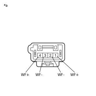
*a
Component without harness connected
(No. 1 Speaker with Box Assembly)
Measure the resistance according to the value(s) in the table below.
Standard Resistance
Tester Connection
Condition
Specified Condition
1 (WF+) - 3 (WF-)
Always
4.0 to 6.4 Ω
2 (WF-) - 4 (WF+)
Always
4.0 to 6.4 Ω
Result
Proceed to
OK
NG