DOOR CLOSER SYSTEM Rear Door Closer LH does not Operate
DESCRIPTION
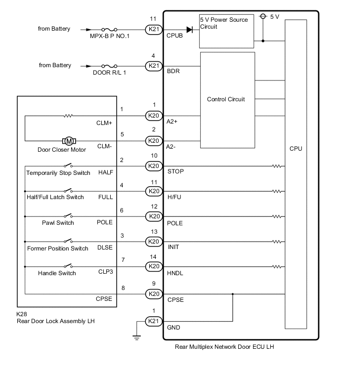
The rear left side door closer controls the rear multiplex network door ECU LH, and operates the door closer motor based on the switch signals in the rear door lock assembly LH.
WIRING DIAGRAM
CAUTION / NOTICE / HINT
Note
Inspect fuses for circuits related to this system before performing the following inspection procedure.
PROCEDURE
-
READ VALUE USING GTS
-
Read the Data List according to the display on the GTS.
Body Electrical > Rear Left Door > Data ListTester Display Measurement Item Range Normal Condition Diagnostic Note Pawl Switch Pawl switch signal ON or OFF ON: Pawl switch is ON
OFF: Pawl switch is OFF
- Closer Position Switch Former position switch ON or OFF ON: Former position switch ON
OFF: Former position switch OFF
- Half/Full-latch Switch Half/full latch switch signal ON or OFF ON: Half/full latch switch ON
OFF: Half/full latch switch OFF
- Closer Stop Switch Temporarily stop switch signal ON or OFF ON: Temporarily stop switch signal ON
OFF: Temporarily stop switch signal OFF
- Outside Handle Switch Handle switch signal ON or OFF ON: Handle switch ON
OFF: Handle switch OFF
-
Body Electrical > Rear Left Door > Data ListTester Display Pawl Switch Closer Position Switch Half/Full-latch Switch Closer Stop Switch Outside Handle Switch OK The switches do not switch ON/OFF according to the door open/close operation. Result Proceed to OK NG
NG 
CHECK HARNESS AND CONNECTOR (REAR MULTIPLEX NETWORK DOOR ECU LH - REAR DOOR LOCK ASSEMBLY LH) Click here
OK 
-
-
CHECK HARNESS AND CONNECTOR (REAR MULTIPLEX NETWORK DOOR ECU LH - BATTERY AND BODY GROUND)
-
Disconnect the K21 rear multiplex network door ECU LH connector.
-
Measure the resistance according to the value(s) in the table below.
Standard Resistance Tester Connection Condition Specified Condition K21-1 (GND) - Body ground Always Below 1 Ω -
Measure the voltage according to the value(s) in the table below.
Standard Voltage Tester Connection Condition Specified Condition K21-4 (BDR) - Body ground Always 11 to 14 V K21-11 (CPUB) - Body ground Always 11 to 14 V Result Proceed to OK NG
NG 
REPAIR OR REPLACE HARNESS OR CONNECTOR
OK
-
-
INSPECT REAR DOOR LOCK ASSEMBLY LH
-
Remove the rear door lock assembly LH.
-
Inspect the rear door lock assembly LH.
Result Proceed to OK NG
NG
REPLACE REAR DOOR LOCK ASSEMBLY LH Click here
OK
-
-
CHECK HARNESS AND CONNECTOR (REAR MULTIPLEX NETWORK DOOR ECU LH - REAR DOOR LOCK ASSEMBLY LH)
-
Disconnect the K20 rear multiplex network door ECU LH connector.
-
Disconnect the K28 rear door lock assembly LH connector.
-
Measure the resistance according to the value(s) in the table below.
Standard Resistance Tester Connection Condition Specified Condition K20-1 (A2+) - K28-1 (CLM+) Always Below 1 Ω K20-2 (A2-) - K28-5 (CLM-) Always Below 1 Ω K20-1 (A2+) or K28-1 (CLM+) - Body ground Always 10 kΩ or higher K20-2 (A2-) or K28-5 (CLM-) - Body ground Always 10 kΩ or higher Result Proceed to OK NG
OK
REPLACE REAR MULTIPLEX NETWORK DOOR ECU LH Click here
NG
REPAIR OR REPLACE HARNESS OR CONNECTOR
-
-
CHECK HARNESS AND CONNECTOR (REAR MULTIPLEX NETWORK DOOR ECU LH - REAR DOOR LOCK ASSEMBLY LH)
-
Disconnect the K20 rear multiplex network door ECU LH connector.
-
Disconnect the K28 rear door lock assembly LH connector.
-
Measure the resistance according to the value(s) in the table below.
Standard Resistance Tester Connection Condition Specified Condition K20-9 (CPSE) - K28-8 (CPSE) Always Below 1 Ω K20-10 (STOP) - K28-2 (HALF) Always Below 1 Ω K20-11 (H/FU) - K28-4 (FULL) Always Below 1 Ω K20-12 (POLE) - K28-6 (POLE) Always Below 1 Ω K20-13 (INIT) - K28-3 (DLSE) Always Below 1 Ω K20-14 (HNDL) - K28-7 (CLP3) Always Below 1 Ω K20-9 (CPSE) or K28-8 (CPSE) - Body ground Always 10 kΩ or higher K20-10 (STOP) or K28-2 (HALF) - Body ground Always 10 kΩ or higher K20-11 (H/FU) or K28-4 (FULL) - Body ground Always 10 kΩ or higher K20-12 (POLE) or K28-6 (POLE) - Body ground Always 10 kΩ or higher K20-13 (INIT) or K28-3 (DLSE) - Body ground Always 10 kΩ or higher K20-14 (HNDL) or K28-7 (CLP3) - Body ground Always 10 kΩ or higher Result Proceed to OK NG
NG
REPAIR OR REPLACE HARNESS OR CONNECTOR
OK
-
-
CHECK REAR DOOR LOCK ASSEMBLY LH
-
Temporarily replace the rear door lock assembly LH with a new or known good one.
-
Check the door closer function is normally.
Result Proceed to OK NG
OK
END (REAR DOOR LOCK ASSEMBLY LH WAS DEFECTIVE)
NG
REPLACE REAR MULTIPLEX NETWORK DOOR ECU LH Click here
-