STEERING GEAR REASSEMBLY
-
INSTALL POWER STEERING CYLINDER TUBE OIL SEAL
-
Install the spacer to the power steering rack housing.
Note
Do not damage the inside of the power steering rack housing.
-
Apply power steering fluid to the lip of a new power steering cylinder tube oil seal.
-
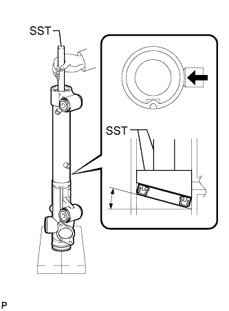
Install the power steering cylinder tube oil seal to the rack housing at an angle.
Note
-
Make sure that the power steering cylinder tube oil seal is installed in the correct direction as shown in the illustration.
-
Install the power steering cylinder tube oil seal at an angle of approximately 20° so that the lowermost part comes to the point, indicated by the arrow in the illustration, to prevent damage to the oil seal when it passes the 2 ports.
-
After passing both ports, proceed by pressing the oil at an angle of 10° and 0° sequentially.
-
-
Using SST, push in the power steering cylinder tube oil seal by hand until the oil seal passes the 2 ports.
- SST
- 09631-00200
- 09950-70010 ( 09951-07360 )
Note
Do not turn the SST when inserting the oil seal.
-
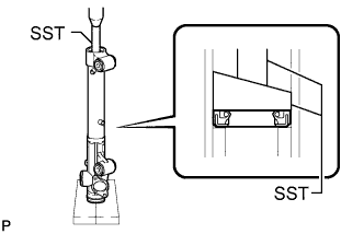
Install SST (09631-00200) to SST (09951-07360) upside down.
- SST
- 09631-00200
- 09950-70010 ( 09951-07360 )
-
Using SST, push the power steering cylinder tube oil seal by hand so that it is level.
- SST
- 09631-00200
- 09950-70010 ( 09951-07360 )
-
Using SST and a press, install the power steering cylinder tube oil seal.
- SST
- 09631-00200
- 09950-70010 ( 09951-07360 )
Tech Tips
Please press cylinder tube oil seal until it sit on the stopper portion.
-
-
INSTALL STEERING RACK PISTON RING
-
Coat a new O-ring with power steering fluid and install it on the steering rack.
-
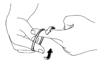
Stretch a new "teflon" ring with your fingers.
Note
Be careful not to overstretch the "teflon" ring.
-
Coat the "teflon" ring with power steering fluid.
-
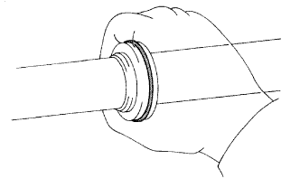
Install the "teflon" ring to the steering rack's groove. Grip the ring to press it into the groove.
-
-
INSTALL POWER STEERING RACK
-
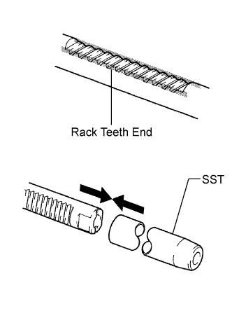
Apply grease to the rack teeth ends.
-
Install SST to the steering rack.
- SST
- 09631-00350
Tech Tips
If necessary, scrape the burrs off the rack teeth end and burnish.
-
Coat SST and the power piston oil seal with power steering fluid.
-
Install the steering rack to the rack housing.
-
Remove SST.
-
Coat SST with power steering fluid.
- SST
- 09631-00350
-
Install SST to the steering rack opposite end.
-
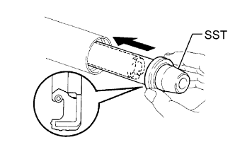
Coat the lip of a new oil seal with power steering fluid. Using SST, install the oil seal to the steering rack.
Note
-
Slide SST and the oil seal straight without tilting them.
-
Make sure to install the oil seal facing in the correct direction.
-
Be careful not to damage the lip of the oil seal.
-
-
Remove SST.
-
-
INSTALL CYLINDER END STOPPER
-
Apply sealant to the stopper.
-
Using a wooden block and hammer, tap in the stopper until it is tightly installed.
Sealant Toyota Genuine Adhesive 1344,Three Bond 1344 or equivalent -
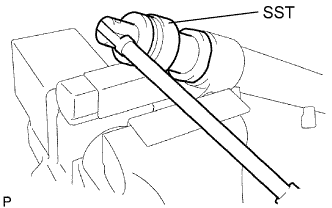
Using SST, tighten the stopper.
- SST
- 09631-20120
- Torque:
- 83 N*m { 841 kgf*cm, 61 ft.*lbf }
-
-
TEST AIR TIGHTNESS
-
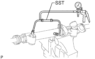
Install SST to the unions of the rack housing.
- SST
- 09631-12071 ( 09633-00010 )
-
Apply 53.33 kPa (400 mmHg, 15.75 in.Hg) of vacuum for about 30 seconds.
-
Check that there is no change in the vacuum.
If there is a change in the vacuum, check the installation of the oil seals.
-
-
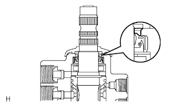
INSTALL POWER STEERING CONTROL VALVE
-
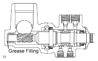
Apply molybdenum disulfide base grease to the needle roller bearing inside the rack housing shown in the illustration.
Volume of grease applied Approximately 2 g (0.07 oz) -
Using a plastic-faced hammer and a sliding handle, lightly tap in 2 new union seats.
Note
Before installing the union seats, remove any dust sticking to the control valve housing.
-
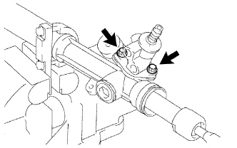
Install a control valve gasket and the control valve with the 2 bolts.
- Torque:
- 18 N*m { 184 kgf*cm, 13 ft.*lbf }
-
-
INSTALL RACK GUIDE
-
Install the rack guide and spring.
-
Apply sealant to 2 or 3 threads of the rack guide spring cap.
Sealant Toyota Genuine Adhesive 1344,Three Bond 1344 or equivalent -
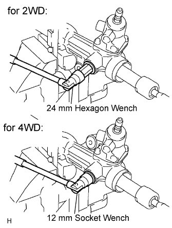
for 2WD:
Using a 24 mm hexagon wrench, temporarily install the spring cap.
-
for 4WD:
Using a 12 mm socket wrench, temporarily install the spring cap.
-
-
ADJUST TOTAL PRELOAD
-
To prevent the steering rack teeth from damaging the lip of the oil seal, temporarily install the RH and LH rack ends.
-
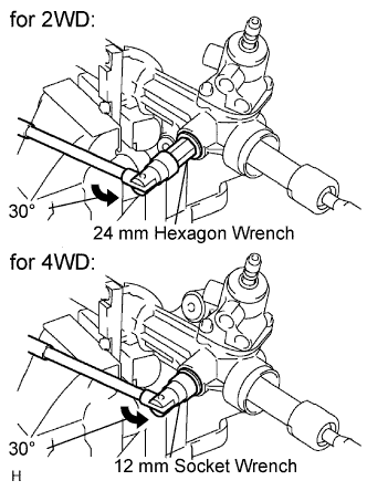
for 2WD:
Using a 24 mm hexagon wrench, tighten the rack guide spring cap.
- Torque:
- 25 N*m { 250 kgf*cm, 18 ft.*lbf }
-
Loosen the cap 30°.
-
for 4WD:
Using a 12 mm socket wrench, tighten the rack guide spring cap.
- Torque:
- 25 N*m { 250 kgf*cm, 18 ft.*lbf }
-
Loosen the cap 30°.
-
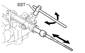
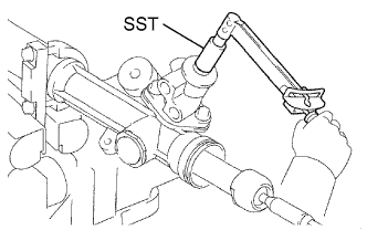
Using SST, turn the control valve shaft right and left 1 or 2 times. The rack end will move in and out.
- SST
- 09616-00011
-
Using a 24 mm hexagon wrench, loosen the cap until the rack guide spring does not function.
-
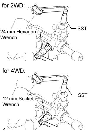
for 2WD:
Using SST, a torque wrench and 24 mm hexagon wrench, tighten the cap until the preload is within the specification.
- SST
- 09616-00011
- Torque:
- Preload (turning)
- 0.8 to 1.6 N*m { 8.2 to 16.3 kgf*cm, 7.1 to 14.2 in.*lbf }
Note
Perform adjustments in the tightening direction of the spring cap.
-
for 4WD:
Using SST, a torque wrench and 12 mm socket wrench, tighten the cap until the preload is within the specification.
- SST
- 09616-00011
- Torque:
- Preload (turning)
- 1.0 to 1.8 N*m { 10.2 to 18.4 kgf*cm, 8.9 to 15.9 in.*lbf }
Note
Perform adjustments in the tightening direction of the spring cap.
-
Apply sealant to 2 or 3 threads of the lock nut.
Sealant Toyota Genuine Adhesive 1344,Three Bond 1344 or equivalent -
Temporarily install the lock nut.
-
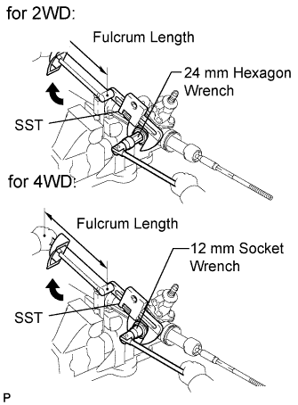
for 2WD:
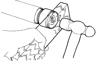
Using a 24 mm hexagon wrench, hold the rack guide spring cap. Using SST, torque the nut.
- SST
- 09922-10010
- Torque:
- 69 N*m { 704 kgf*cm, 51 ft.*lbf, for use without SST }
- 51 N*m { 516 kgf*cm, 37 ft.*lbf, for use with SST }
Note
Rotate SST in the direction shown in the illustration.
Tech Tips
Use a torque wrench with a fulcrum length of 345 mm (13.6 in.).
-
for 4WD:
Using a 12 mm socket wrench, hold the rack guide spring cap. Using SST, torque the nut.
- SST
- 09922-10010
- Torque:
- 69 N*m { 704 kgf*cm, 51 ft.*lbf, for use without SST }
- 51 N*m { 516 kgf*cm, 37 ft.*lbf, for use with SST }
Note
Rotate SST in the direction shown in the illustration.
Tech Tips
Use a torque wrench with a fulcrum length of 345 mm (13.6 in.).
-
Using SST, recheck the total preload.
- SST
- 09616-00011
- Torque:
- Preload for 2WD (turning)
- 0.8 to 1.6 N*m { 8.2 to 1.6 kgf*cm, 1.1 to 14.2 in.*lbf }
- Preload for 4WD (turning)
- 1.0 to 1.8 N*m { 10.2 to 18.4 kgf*cm, 8.9 to 15.9 in.*lbf }
-
Remove the RH and LH rack ends.
-
-
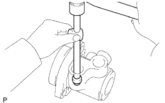
INSPECT POWER STEERING RACK
-
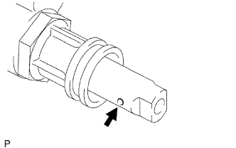
Insert a wire 20 mm (0.787 in.) into the vent hole of the steering rack, and ensure that the vent hole is not clogged with grease.
Note
If the hole is clogged, the pressure inside the boot will change after it is assembled and the steering wheel is turned.
-
-
INSTALL STEERING RACK END SUB-ASSEMBLY
-
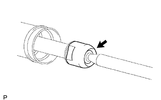
Install 2 new claw washers to the power steering rack while aligning the notch on the steering rack end with the claw.
-
Temporarily install the 2 steering rack ends to the power steering rack.
-
Fill up the ball joint of the steering rack ends with MP grease.
-
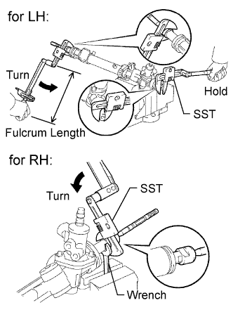
Using SST, install the power steering rack end (LH side) to the power steering rack.
- SST
- 09922-10010
- Torque:
- 103 N*m { 1050 kgf*cm, 76 ft.*lbf, for use without SST }
- 94 N*m { 959 kgf*cm, 69 ft.*lbf, for use with SST }
Note
-
Rotate SST in the direction shown in the illustration.
-
Use a torque wrench with a fulcrum length of 345 mm (13.6 in.).
-
Using SST and a wrench, install the power steering rack (LH side).
- SST
- 09922-10010
- Torque:
- 103 N*m { 1050 kgf*cm, 76 ft.*lbf, for use without SST }
- 94 N*m { 959 kgf*cm, 69 ft.*lbf, for use with SST }
Note
-
Rotate SST in the direction shown in the illustration.
-
Use a torque wrench with a fulcrum length of 345 mm (13.6 in.).
-
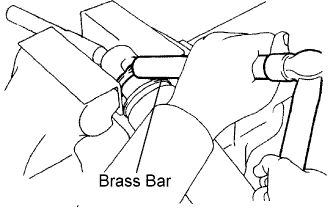
Using a brass bar and hammer, stake the 2 claw washers (LH and RH side).
Note
Do not strike the steering rack.
-
-
INSTALL STEERING RACK BOOT LH
-
Install the boot.
Note
Be careful not to damage or twist the boot.
-
-
INSTALL STEERING RACK BOOT RH
Tech Tips
Use the same procedures described for the LH side.
-
INSTALL STEERING RACK BOOT CLAMP LH
-
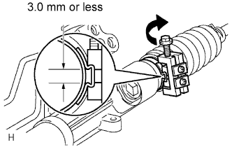
Using SST, tighten the rack boot clamp, as shown in the illustration.
- SST
- 09240-00020
- 09521-24010
Clearance 3.0 mm (0.118 in.) or less Note
Be careful not to damage the boot.
Tech Tips
Mark the RH and LH boots.
Note
If the clamp is damaged, replace it with a new one.
-
-
INSTALL STEERING RACK BOOT CLAMP RH
Tech Tips
Use the same procedures described for the LH side.
-
INSTALL STEERING RACK BOOT CLIP LH
-
Using pliers, install the clip.
-
-
INSTALL STEERING RACK BOOT CLIP RH
Tech Tips
Use the same procedures described for the LH side.
-
INSTALL POWER STEERING GEAR ASSEMBLY
-
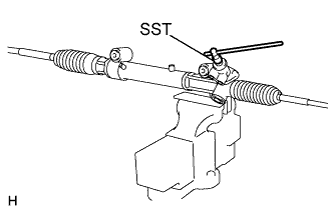
Using SST, check that the rack boot stretches smoothly when the control valve shaft is being rotated.
- SST
- 09616-00011
-
Apply MP grease as shown in the illustration.
-
Install the dust cover.
-
-
INSTALL STEERING TURN PRESSURE TUBE (for 2WD)
-
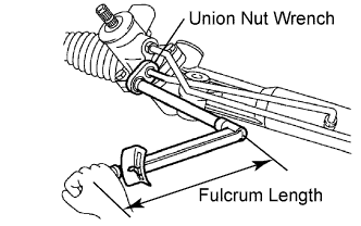
Apply power steering fluid to 2 new O-rings. Using a union nut wrench, install the 2 O-rings and the LH turn pressure tube.
- Torque:
- 13 N*m { 127 kgf*cm, 9 ft.*lbf }
Note
Use the formula to calculate special torque values for situations where a union nut wrench is combined with a torque wrench Click here.
-
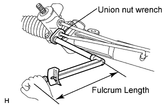
Apply power steering fluid to 2 new O-rings. Using a union nut wrench, install the 2 O-rings and the RH turn pressure tube.
- Torque:
- 13 N*m { 127 kgf*cm, 9 ft.*lbf }
Note
Use the formula to calculate special torque values for situations where a union nut wrench is combined with a torque wrench Click here.
-
-
INSTALL STEERING TURN PRESSURE TUBE (for 4WD)
-
Apply power steering fluid to 2 new O-rings. Using a union nut wrench, install the 2 O-rings and the LH turn pressure tube.
- Torque:
- 13 N*m { 127 kgf*cm, 9 ft.*lbf }
Note
Use the formula to calculate special torque values for situations where a union nut wrench is combined with a torque wrench Click here.
-
Apply power steering fluid to 2 new O-ring. Using a union nut wrench, install the O-ring and one side of the RH turn pressure tube.
- Torque:
- 13 N*m { 127 kgf*cm, 9 ft.*lbf }
Note
Use the formula to calculate special torque values for situations where a union nut wrench is combined with a torque wrench Click here.
-
Apply power steering fluid to new 2 gaskets. Install the 2 gaskets and the RH turn pressure tube.
- Torque:
- 29 N*m { 300 kgf*cm, 22 ft.*lbf }
-