LIGHTING SYSTEM Vehicle Speed Signal Circuit
| DTC Code | DTC Name |
|---|---|
| Vehicle Speed Signal Circuit |
DESCRIPTION
The headlight leveling ECU receives the vehicle speed signal from the combination meter.
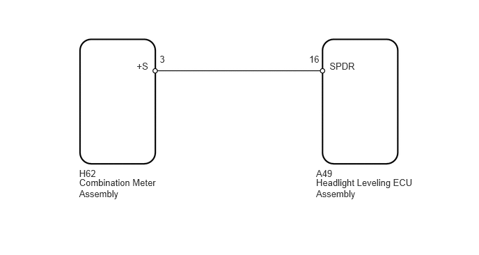
WIRING DIAGRAM
CAUTION / NOTICE / HINT
After replacing the headlight leveling ECU, initialization of the ECU is necessary (Click here).
PROCEDURE
READ VALUE USING INTELLIGENT TESTER (VEHICLE SPEED)
Using the intelligent tester, read the Data List (Click here).
Table 1. HL Auto Leveling Tester Display
Measurement Item/Range
Normal Condition
Diagnostic Note
Vehicle Speed
Vehicle speed / 0 to 327.67 km/h
A value similar to the actual vehicle speed is displayed
-
OK
The display is as specified in the normal condition column.
CHECK HARNESS AND CONNECTOR (COMBINATION METER ASSEMBLY - HEADLIGHT LEVELING ECU ASSEMBLY)
-
Disconnect the H62 combination meter connector.
Disconnect the A49 headlight leveling ECU connector.
Measure the resistance according to the value(s) in the table below.
Standard Resistance
Tester Connection
Condition
Specified Condition
H62-3 (+S) - A49-16 (SPDR)
Always
Below 1 Ω
H62-3 (+S) - Body ground
Always
10 kΩ or higher
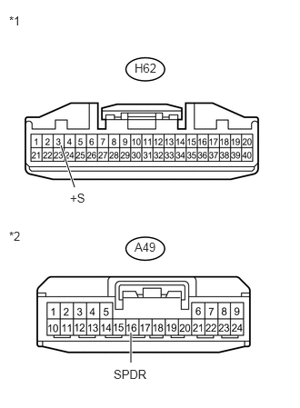
Table 2. Text in Illustration *1
Front view of wire harness connector
(to Combination Meter Assembly)
*2
Front view of wire harness connector
(to Headlight Leveling ECU Assembly)
REPAIR OR REPLACE HARNESS OR CONNECTOR
-
CHECK COMBINATION METER ASSEMBLY
-
Remove the combination meter with its connector still connected (Click here).
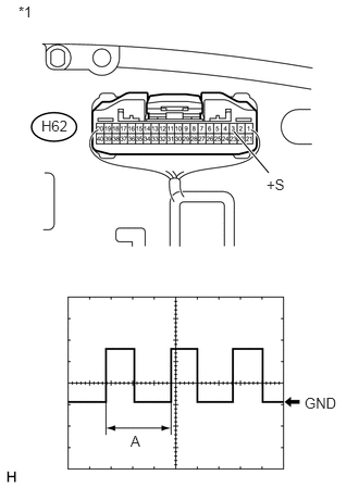
Table 3. Text in Illustration *1
Component with harness connected
(Combination Meter Assembly)
Connect an oscilloscope to the combination meter connector.
Check the waveform.
Table 4. Measurement Condition Item
Content
Terminal No. (Symbol)
H62-3 (+S) - Body ground
Tool setting
5 V/DIV., 20 ms./DIV.
Condition
Vehicle is driven at approximately 20 km/h (12 mph)
OK
Waveform is as shown in the illustration.
Tip:When the system is functioning normally, one wheel revolution generates 4 pulses. As the vehicle speed increases, the width indicated by (A) in the illustration narrows.
Table 5. Result Result
Proceed to
OK (for LHD)
A
OK (for RHD)
B
NG
C
-