FRONT EVAPORATOR TEMPERATURE SENSOR INSTALLATION
PROCEDURE
-
INSTALL NO. 1 COOLER THERMISTOR
-
for HFC-134a (R134a):
-
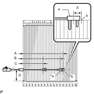
Text in Illustration *a Fixed Part *b Sensor Part Install the No. 1 cooler thermistor as shown in the illustration.
Part Length A 175 mm 6.89 in. B 161.6 mm 6.36 in. C 87.9 mm 3.46 in. D 50 mm 1.97 in. Note
-
Be sure to insert the thermistor only once because reinserting it into the same position will not allow it to be firmly secured.
-
When reusing the evaporator, insert the thermistor one row next to the one that has been used previously (X in the illustration).
-
After inserting the thermistor, do not apply excessive force to the wire.
-
Directly insert the thermistor until the edge of plastic case "a" comes into contact with evaporator "b".
-
-
-
for HFO-1234yf (R1234yf):
-
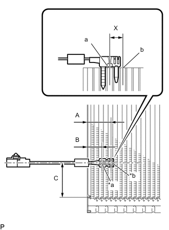
Text in Illustration *a Fixed Part *b Sensor Part Install the No. 1 cooler thermistor as shown in the illustration.
Part Length A 34.3 mm 1.35 in. B 20.9 mm 0.823 in. C 50 mm 1.97 in. Note
-
Be sure to insert the thermistor only once because reinserting it into the same position will not allow it to be firmly secured.
-
When reusing the evaporator, insert the thermistor one row next to the one that has been used previously (X in the illustration).
-
After inserting the thermistor, do not apply excessive force to the wire.
-
Directly insert the thermistor until the edge of plastic case "a" comes into contact with evaporator "b".
-
-
-
-
INSTALL NO. 1 COOLER EVAPORATOR SUB-ASSEMBLY
-
INSTALL COOLER EXPANSION VALVE
-
INSTALL BLOWER ASSEMBLY
-
INSTALL AIR CONDITIONING UNIT ASSEMBLY