POWER BACK DOOR SYSTEM, Diagnostic DTC:B2202
| DTC Code | DTC Name |
|---|---|
| B2202 | Lost Communication with Emblem Sensor |
DESCRIPTION
This DTC is stored when the multiplex network door ECU detects a communication malfunction between the multiplex network door ECU and the rear emblem sensor assembly.
| DTC No. | Detection Item | DTC Detection Condition | Trouble Area |
|---|---|---|---|
| B2202 | Lost Communication with Emblem Sensor | Communication malfunction detected between the multiplex network door ECU and rear emblem sensor assembly |
|
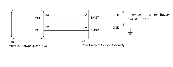
WIRING DIAGRAM
CAUTION / NOTICE / HINT
Note
-
Before troubleshooting, make sure that the rear emblem sensor assembly is not damaged.
-
Before troubleshooting, be sure to read Precautions for Touchless Power Back Door.
-
If the multiplex network door ECU has been removed and installed or replaced, or if any of the connectors has been disconnected, initialize the power back door system.
-
Inspect the fuses for circuits related to this system before performing the following procedure.
PROCEDURE
-
CHECK FOR DTC
-
Clear the DTCs.
Body Electrical > Back Door > Clear DTCs -
Check for DTCs.
Body Electrical > Back Door > Trouble CodesOK DTC B2202 is not output. Result Proceed to OK NG
OK 
USE SIMULATION METHOD TO CHECK Click here
NG 
-
-
CHECK HARNESS AND CONNECTOR (REAR EMBLEM SENSOR ASSEMBLY - BATTERY AND BODY GROUND)
-
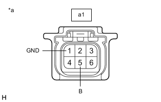
*a Front view of wire harness connector
(to Rear Emblem Sensor Assembly)
Disconnect the a1 rear emblem sensor assembly connector.
-
Measure the resistance according to the value(s) in the table below.
Standard Resistance Tester Connection Condition Specified Condition a1-1 (GND) - Body ground Always Below 1 Ω -
Measure the voltage according to the value(s) in the table below.
Standard Voltage Tester Connection Condition Specified Condition a1-5 (B) - Body ground Always 11 to 14 V Result Proceed to OK NG
NG
REPAIR OR REPLACE HARNESS OR CONNECTOR
OK
-
-
CHECK HARNESS AND CONNECTOR (MULTIPLEX NETWORK DOOR ECU - REAR EMBLEM SENSOR ASSEMBLY)
-
Disconnect the Z16 multiplex network door ECU connector.
-
Disconnect the a1 rear emblem sensor assembly connector.
-
Measure the resistance according to the value(s) in the table below.
Standard Resistance Tester Connection Condition Specified Condition Z16-33 (EMSR) - a1-2 (EMST) Always Below 1 Ω Z16-32 (EMST) - a1-4 (EMSR) Always Below 1 Ω Z16-33 (EMSR) or a1-2 (EMST) - Body ground Always 10 kΩ or higher Z16-32 (EMST) or a1-4 (EMSR) - Body ground Always 10 kΩ or higher Result Proceed to OK NG
NG
REPAIR OR REPLACE HARNESS OR CONNECTOR
OK
-
-
REPLACE REAR EMBLEM SENSOR ASSEMBLY
-
Temporarily replace the rear emblem sensor assembly with a new or known good one.
Result Proceed to NEXT
NEXT
-
-
CHECK FOR DTC
-
Clear the DTCs.
Body Electrical > Back Door > Clear DTCs -
Check for DTCs.
Body Electrical > Back Door > Trouble CodesOK DTC B2202 is not output. Result Proceed to OK NG
OK
END (REAR EMBLEM SENSOR ASSEMBLY WAS DEFECTIVE)
NG
REPLACE MULTIPLEX NETWORK DOOR ECU Click here
-