DIFFERENTIAL SIDE GEAR SHAFT INSTALLATION
PROCEDURE
INSTALL DIFFERENTIAL SIDE GEAR SHAFT DUST COVER LH
for LH Side:
-
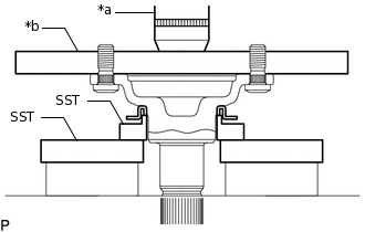
*a
Press
*b
Steel Plate
Using SST, a steel plate and a press, install a new dust cover to the differential side gear shaft sub-assembly.
09527-21011
09726-40010
Note:Make sure that the edge of the dust cover is securely installed to the differential side gear shaft sub-assembly.
Do not damage the dust cover.
-
for RH Side:
-
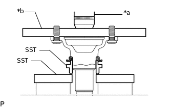
*a
Press
*b
Steel Plate
Using SST, a steel plate and a press, install a new dust cover to the differential side gear shaft sub-assembly.
09309-14010
09527-20011
Note:Make sure that the edge of the dust cover is securely installed to the differential side gear shaft sub-assembly.
Do not damage the dust cover.
-
INSTALL DIFFERENTIAL SIDE GEAR SHAFT SUB-ASSEMBLY LH
Install a new differential side gear shaft snap ring to the differential side gear shaft sub-assembly.
Using SST, install the differential side gear shaft sub-assembly to the rear traction motor with transaxle assembly.
09520-24010
09520-04010
09520-32040
Note:Position the differential side gear shaft snap ring with the opening facing downward.
Do not tap the differential side gear shaft sub-assembly at an angle. If the differential side gear shaft sub-assembly is tapped at an angle, replace the differential side gear shaft snap ring with a new one.
Do not damage the rear transaxle side gear oil seal.
-
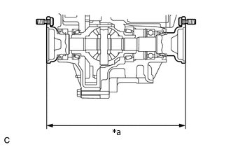
*a
272.9 mm (10.744 in.) or Less
Using a vernier caliper, measure the distance between the right and left differential side gear shaft sub-assemblies as shown in the illustration.
Standard Distance
272.9 mm (10.744 in.) or Less
INSTALL REAR DRIVE SHAFT ASSEMBLY
ADD HYBRID TRANSAXLE FLUID
INSPECT HYBRID TRANSAXLE FLUID