PROPELLER SHAFT ASSEMBLY INSTALLATION

PROCEDURE
-
TEMPORARILY INSTALL PROPELLER WITH CENTER BEARING SHAFT ASSEMBLY
-
Completely remove any oil or the like and clean the contact surfaces of the rear transfer output shaft sub-assembly and propeller with center bearing shaft assembly.
-
Completely remove any oil or the like and clean the contact surfaces of the transmission coupling assembly and propeller with center bearing shaft assembly.
-
Align the matchmarks of the transfer assembly and propeller with center bearing shaft assembly.
-
Temporarily install the propeller with center bearing shaft assembly with the 4 nuts and 4 washers.
-
Align the matchmarks of the differential carrier assembly and propeller with center bearing shaft assembly.
-
Temporarily install the propeller with center bearing shaft assembly with the 4 nuts and 4 washers.
-
for TMC Made:
-
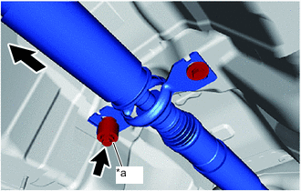
*a Bolt with Damper 
Front of Vehicle Temporarily install the center support bearing and center No. 2 support bearing washer with the 2 bolts.
Note
Install the 2 bolts to the center support bearing as shown in the illustration.
-
-
for TMMT Made:
-
Temporarily install the center support bearing and center No. 2 support bearing washer with the 2 bolts.
-
-
-
TIGHTEN PROPELLER WITH CENTER BEARING SHAFT ASSEMBLY
-
Tighten the 4 nuts of the propeller with center bearing shaft assembly and transfer assembly to the torque specification.
- Torque:
- 35 N*m { 357 kgf*cm, 26 ft.*lbf }
-
Tighten the 4 nuts of the propeller with center bearing shaft assembly and differential carrier assembly to the torque specification.
- Torque:
- 35 N*m { 357 kgf*cm, 26 ft.*lbf }
-
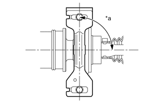
*a 90° Check that the center line of the center support bearing housing is perpendicular to the axis of the propeller shaft.
-
Tighten the 2 bolts of the center support bearing to the torque specification.
- Torque:
- 36.8 N*m { 375 kgf*cm, 27 ft.*lbf }
-
-
INSPECT AND ADJUST JOINT ANGLE
Note
Perform the measurement with a 4 post lift or pit so that the vehicle is supported by all 4 wheels as if it were on the ground.
-
Before the angle measurement, stabilize each part by performing procedures like those described below.
-
Rotate the propeller shaft several times by hand.
-
Set the jack to the differential, and raise and lower the differential.
-
-
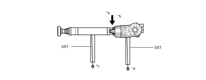
Using SST and a straightedge, measure the angle of the transfer flange (angle D) and the angle of the intermediate shaft (angle A).
- SST
- 09370-50010
Note
Make sure the straightedge and SST are at a right angle.
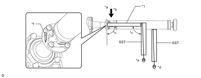
*1 Straightedge - - *a No. 1 Joint Angle *b D - A *c 90° *d Angle A *e Angle D *f Angle D Measurement Position
-
Subtract the measured angle of the intermediate shaft (angle A) from the measured angle of the transfer flange (angle D) to obtain the No. 1 joint angle.
No. 1 Joint Angle Measurement Position No. 1 Joint Angle D - A -2°00' +/- 30'
-
Using SST, measure the angle of the intermediate shaft (angle A) and the angle of the propeller shaft (angle B).
- SST
- 09370-50010
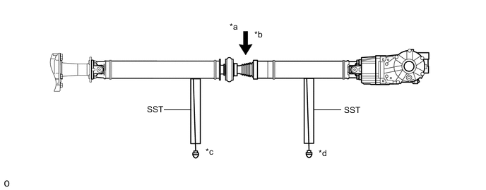
*a No. 2 Joint Angle *b A - B *c Angle A *d Angle B
-
Subtract the measured angle of the intermediate shaft (angle A) from the measured angle of the transfer flange (angle B) to obtain the No. 2 joint angle.
No. 2 Joint Angle Measurement Position No. 2 Joint Angle A - B 1°54' +/- 30'
-
Using SST, measure the angle of the propeller shaft (angle B) and the angle of the rear differential (angle C).
- SST
- 09370-50010
*a No. 3 Joint Angle *b B - C *c Angle B *d Angle C
-
Subtract the measured angle of the propeller shaft (angle B) from the measured angle of the rear differential (angle C) to obtain the No. 3 joint angle.
No. 3 Joint Angle Measurement Position No. 3 Joint Angle B - C 2°00' +/- 30'
-
If the measured angle of the propeller shaft is not within the specified range, or there is vibration or noise, use the following procedure to adjust the propeller shaft.
-
Support the propeller shaft with a jack.
-
Remove the 2 center bearing mounting bolts.
-
Slowly lower the jack and disconnect the center bearing.
-
Select an appropriate adjusting washer thickness from the table below, and obtain a washer set.
Standard Adjusting Washer Part No. Thickness mm (in.) 90201-10123 2.0 mm (0.0787 in.) 90201-10081 4.5 mm (0.177 in.) 90201-10083 6.5 mm (0.256 in.) 90201-10084 9.0 mm (0.354 in.) 90201-10085 11.0 mm (0.433 in.) Tech Tips
-
Use washers of the same thickness on the left and right sides.
-
Do not use 2 or more washers stacked together.
-
Install the washers.
-
-
-
-
INSTALL FRONT NO. 2 FLOOR HEAT INSULATOR
-
Install the front No. 2 floor heat insulator to the vehicle body with the 2 clips.
-
-
INSTALL EXHAUST PIPE ASSEMBLY