METER / GAUGE SYSTEM
-
OUTLINE
-
The following analog type combination meter assembly has been provided depending on the specifications.
-
Combination meter assembly with segment type multi-information display
-
Combination meter assembly with digital speedometer and segment type multi-information display
-
Combination meter assembly with TFT LCD type multi-information display
-
-
A segment LCD type multi-information display whose display items can be changed by pressing the ODO/TRIP switch or DISP switch and shift position indicator lights are provided in the Liquid Crystal Display (LCD).
-
A TFT LCD type multi-information display whose display items can be changed by pressing the ODO/TRIP switch or steering pad switch assembly and display such as shift position indicator lights are provided in the Thin Film Transistor Liquid Crystal Display (TFT LCD).
-
A DISP switch*and ODO/TRIP switch for switching the display on the multi-information display have been installed in the trip switch on the right side of the combination meter assembly.
-
Digital speedometer display as well as rev indicator/red zone indicators have been installed, depending on the specification.
-
The combination meter assembly has a built-in meter ECU and buzzer.
-
All the meters, gauges, indicator lights and warning lights use LEDs to reduce the consumption of electrical energy.
-
The combination meter assembly displays the odometer or trip meter when the ignition is off by activation of the ODO/TRIP switch.
Tech Tips
*: Except Models with TFT LCD type multi-information display
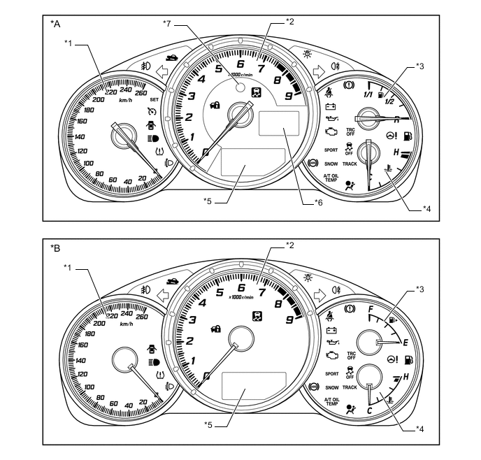
Text in Illustration (Models with km/h: ) *A Models with Digital Speedometer Display *B Models without Digital Speedometer Display *1 Speedometer *2 Tachometer *3 Fuel Gauge *4 Water Temperature Gauge *5 Segment Type Multi-information Display *6 Digital Speedometer Display *7 Rev Indicator/Red Zone Indicator - - 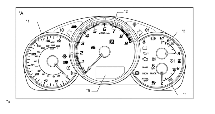
Text in Illustration (Models with MPH and km/h: ) *A Models without Digital Speedometer Display - - *1 Speedometer *2 Tachometer *3 Fuel Gauge *4 Water Temperature Gauge *5 Segment Type Multi-information Display - - *a The illustrations shown are examples only. - - 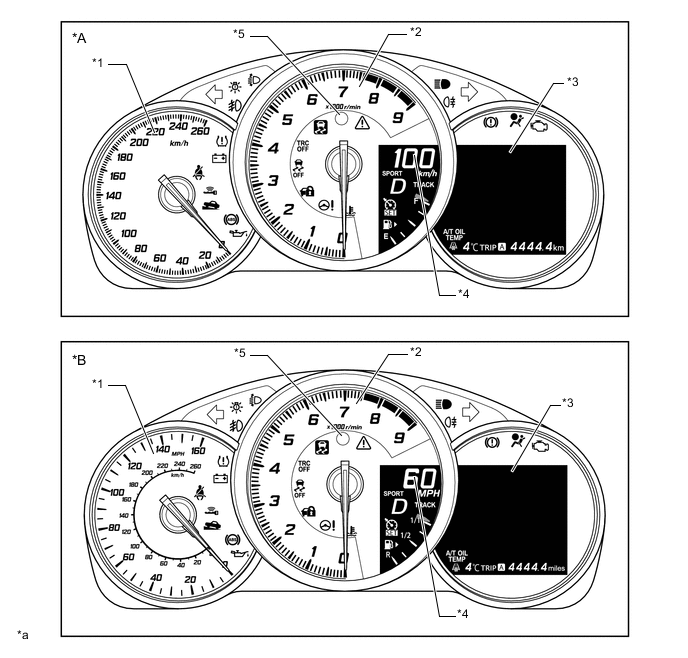
Text in Illustration (Models with TFT LCD Type Multi-information Display) *A Models with km/h Type Combination Meter Assembly B Models with MPH and km/h Type Combination Meter Assembly *1 Speedometer *2 Tachometer *3 TFT Type Multi-information Display *4 Digital Speedometer Display *5 Rev Indicator/Red Zone Indicator - - *a The illustrations shown are examples only. - - -
An intermediate gauge (10 km/h increment) is adopted for the speedometer of the MPH and km/h type combination meter assembly for some specifications.
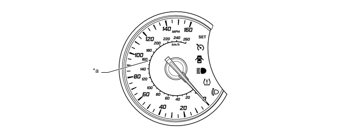
Text in Illustration *a Intermediate Gauge - -
-
-
PRECAUTION
-
Ignition Switch Expressions
-
The type of ignition switch used on this model differs depending on the specifications of the vehicle. The expressions listed in the table below are used in this section.
Expression Ignition Switch (Ignition or Starter Switch Assembly)
(Position)
Engine Switch (Push Start Switch)
(Condition)
Ignition Switch off LOCK Off Ignition Switch ACC ACC On (ACC) Ignition Switch ON ON On (IG) Engine Start START Start
-
-